2= CCW/CW: using positive pulse and negative pulse
[Initial value] 0 (Pulse/direction)
[Setting range] 0 to 2
[Basic setting]
Pulse train command
Rotation direction
Select rotation direction of pulse command input
0: CCW Negative direction
1: CW Positive direction
[Initial value] 1 (CW Positive direction)
[Setting range] 0 or 1
[Basic setting]
With(out) use of
automatic command
interpolation for division/
multiplication
When setting command division/ multiplication, the command will be
processed by smoothing interpolation automatically.
0= Disable
1= Enable
[Initial setting] 1 (Enable)
[Setting range] 0 or 1
[Basic setting]
Selection of Pulse train
input logic
Select the logic for pulse train input.
0= Positive logic : Up counting from Low to High
1= Negative logic: Downing counting from High to Low
[Initial setting] 0 (Positive logic)
[Setting range] 0 or 1
[Basic setting]
Pulse command input
filter selection
The function of input filter is to reduce the fault caused by noise. Select the
pulse width of passing pulse command input.
0= No filter
1= Pulse width 25ns
2= Pulse width 50ns
3= Pulse width 100ns
4= Pulse width 150ns
5= Pulse width 200ns
6= Pulse width 300ns
7= Pulse width 400ns
8= Pulse width 600ns
9= Pulse width 800ns
10= Pulse width
1000ns
11= Pulse width 1200ns
12= Pulse width 1600ns
13= Pulse width 2000ns
14= Pulse width 2300ns
15= Pulse width 3100ns
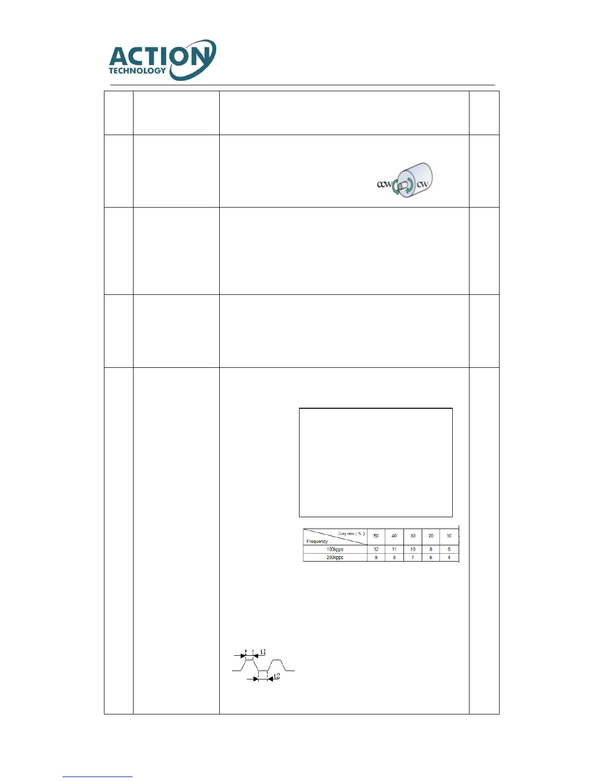
When the input frequency is high, please set the small passing pulse width. To
improve interference immunity, please set the large passing pulse width.
When pulse command is open collector
circuit, it is recommended to set the best
filter. The following table indicates the
corresponding filter optimum value between
input pulse frequency and pulse duty ratio.
Select the best value according to input pulse
frequency and pulse duty ratio.