Do you have a question about the ACU-RITE 200S READOUTS and is the answer not in the manual?
Explains the functions available through soft keys on the 200S readout.
Steps to access and modify the readout's machine parameter settings.
Information about the software version displayed on the initial power-up screen.
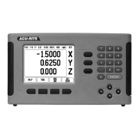
Describes the availability of the 200S DRO in two and three axis configurations.
Explains the meaning of different symbols used in the manual for notes and warnings.
Shows how soft keys and hard keys are represented in the manual's text.
Outlines the coverage and limitations of the ACU-RITE product warranty.
Defines datums and their role in establishing coordinate systems for workpiece positioning.
Explains the terms for tool position, target position, and the remaining distance to the target.
Describes how each position on a workpiece is identified by its unique absolute coordinates.
Explains referencing positions to the preceding nominal position using incremental coordinates.
Defines the 0.0° position and reference axes for angular measurements in different planes.
Explains how the reading head feeds back machine axis movement to the 200S for position calculation.
Details the function of reference marks on encoders for re-establishing datum positions after power interruptions.
Describes the different elements and areas of the 200S readout display screen.
Explains how to navigate through menus, fields, and functions using the keypad and soft keys.
Details the initial power-up sequence and first-time configuration process for the 200S.
Explains the 200S reference mark feature for re-establishing axis positions after a power cycle.
Describes how to operate the 200S without using or crossing reference marks.
Explains how to enable or disable the reference mark function for position recovery.
How to use the ABS/INC soft key to toggle between Actual Value and Distance-To-Go modes.
Guides on how to view and change job-specific setup parameters like units and scale factor.
Explains how to set the preferred display units and format for measurements.
Describes how to use the scale factor to enlarge or reduce the displayed part size.
Explains how a scale factor of -1.00 creates a mirror image of the part.
Details setting diameter, length offset, and units for the edge finder in milling applications.
How to select axes for display in radius or diameter values, especially for turning.
How to configure probe measurement values for output via the serial port.
How to configure the bar graph warning for proximity to zero in Distance-To-Go mode.
How to configure which parameters are displayed in the segmented Status Bar at the top of the screen.
Explains the functionality of the job clock as a stopwatch for tracking elapsed time.
How to set up external switches (pendant, foot switch) for functions like Data Output, Zero, and Next Hole.
How to adjust LCD brightness, contrast, and set the display saver idle time.
How to change the display language of the 200S readout.
How to import or export Job and Installation Setup parameters using the serial port.
Explains how to view the main operating screen layout and its components.
Describes the toggle function of the SET/ZERO soft key for axis operations.
How to use the Distance-To-Go mode with incremental positioning for presets.
How to use the Actual Value mode with absolute positioning for datum setting.
Lists and explains the soft keys available for milling operations.
How to use the TOOL soft key to access the tool table for entering tool parameters.
Describes the 200S tool table for storing diameter and length offset information for up to 16 tools.
Explains how to enter workpiece dimensions and tool radius offsets for compensation.
How to interpret and use the sign for length differences when setting tool offsets.
Steps to select and call a tool from the tool table for use in milling.
Defines datum settings and how they relate axis positions to display values.
Explains how to use probing functions with a tool or edge finder to set datum points.
Describes how to use probing functions with a tool to set datum points by touching workpiece edges.
A step-by-step example of probing a workpiece edge to set it as a datum.
How to use absolute positioning to preset distances for milling operations.
How to use incremental positioning to drill holes by traversing to a display value of zero.
Explains the use of the 1/2 soft key to find the centerline or midpoint between two locations.
Lists and explains the soft keys used for Circle and Linear Pattern features.
How to define circle or linear hole patterns and the required information for each.
Details the information needed to define a linear hole pattern, including type, spacing, and angles.
How to execute a circle or linear pattern and the soft keys available during execution.
Lists and explains the soft keys available for Incline and Arc Milling features.
Explains how to define Incline and Arc Mill entry forms, including plane selection and point definition.
Details the input fields required for defining an Incline Mill operation.
Details the input fields required for defining an Arc Mill operation.
Lists the soft keys used for entering data for Incline and Arc Milling operations.
Explains how to specify the flat surface to be milled using the Incline Milling form.
Explains how to specify the curved surface to be milled using the Arc Milling form.
Lists the soft keys available during the execution of Incline or Arc Milling features.
Explains the icon indicating diameter value display versus radius value display.
Describes the 200S tool table for storing dimensional offsets for up to 16 tools in turning.
Steps to select and call a tool from the tool table for use in turning.
How to enter tool offsets using the TOOL/SET form by touching the workpiece.
Explains datum settings and how to set datum points for turning operations.
A step-by-step example of setting a workpiece datum using the DATUM soft key.
How to use the LOCK AXIS function to set datums when the workpiece diameter is unknown.
How to switch between radius and diameter display modes for lathe parts.
Provides a method for coupling Z0 and Z axes positions on 3 or 4 axis systems for turning.
Steps to couple Z0 and Z axes, displaying the sum on one axis and blanking the other.
How to disable Z coupling by pressing the blank axis key to restore individual displays.
Details how to access and set up installation parameters protected by a passcode.
How to configure encoder settings like resolution, type, count direction, and reference mark.
Further details on selecting encoder resolution and setting count direction.
How to select axes for display and define their order and coupling.
Explains how to compensate for errors caused by machine mechanics like ball screws or axis deflection.
How to apply linear error compensation using a single correction factor based on measured deviations.
How to apply non-linear error compensation using a table of correction points.
Steps to create a new non-linear error compensation table, defining spacing and start points.
How to view, edit, and enter error values into the compensation table.
How to compensate for position errors caused by lead screw clearances in rotary encoders.
Configuration settings for the serial port, including baud rate, parity, data bits, and stop bits.
How to set the user application (Mill/Turn) and the number of axes for the readout.
How to test the functionality of each keypad switch by observing on-screen feedback.
How to test the connected edge finder by touching a part and observing the display.
How to test the display by cycling through solid black, solid white, and normal views.
Guidance on mounting the DRO unit using its tilt/swivel feature.
Specifies voltage, power, frequency, and fuse requirements for the DRO.
Details operating and storage temperature ranges, and mechanical weight.
Instructions for connecting the protective conductor to the machine ground for safety.
Recommendations for cleaning and maintaining the DRO unit.
Shows the pin assignments for connecting an electronic edge finder to the DRO.
Provides pin assignments for wiring serial communication cables for the DRO.
Examples and explanations of data output formats using external signals.
Example of data output for a rotary axis using decimal degrees format.
Example of data output for a rotary axis using degrees/minutes/seconds format.
Explains data output when initiated by an edge finder signal, providing examples.
Example showing data output format for a probing function on the Y axis using an edge finder.
Example showing data output format for a centerline probing function on the X axis.
Example showing data output format for a circle center probing function and diameter.
Detailed physical dimensions and diagrams of the 200S readout unit.