Valve lnstallation
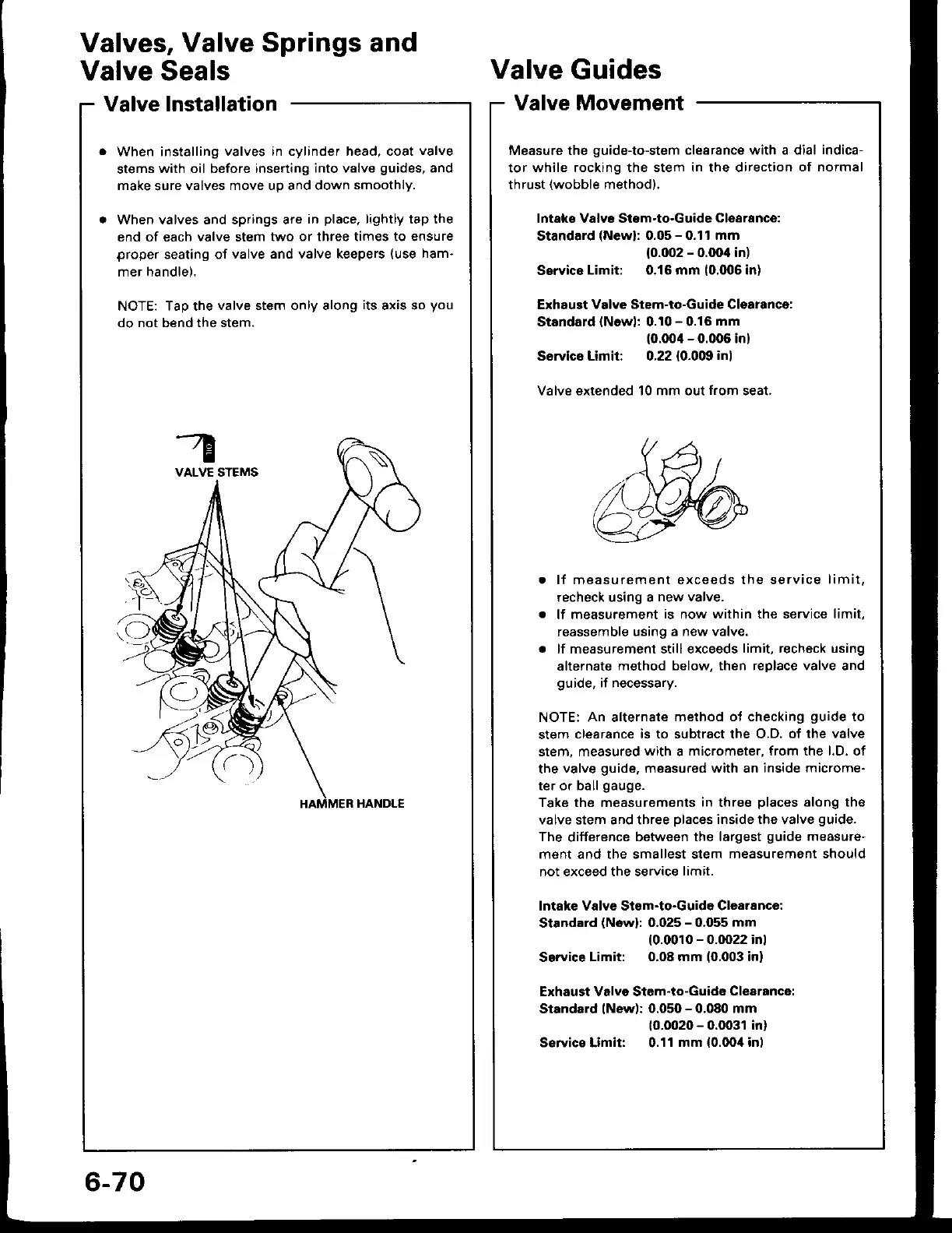
When installing
valves in cylinder head, coat
valve
stems
with oil before inserting
into valve
guides,
and
make
sure
valves move up and down
smoothly.
When valves and springs are
in
place,
lightly tap the
end of each valve stem
two or three times to ensure
proper
seating of
valve and valve keepers
(use
ham-
mer handle).
NOTE: Tap the
valve stem only along
its
axis so
you
do not bend the stem.
Valves,
Valve Springs and
Valve Seals
Valve
Guides
Valve Movement
Measure the
guide-to-stem
clearance with a dial indica-
tor
while rocking the stem in the direction
of normal
thrust
(wobble
method).
lntaks Valvr Stom-to-Guide
Clearance:
Standard
(Newl:
0.05
-
0.11 mm
{0.002
-
0.OO'l in)
Ssrvice
Limit: 0.16 mm
(0.006
in)
Exhaugt
Vdve Stem-to-Guide Clsarancg:
Standald
lNowl:
0.10
-
0.16
mm
(0.00'l
-
0.006 in)
Sorvics Limit: 0.22 {0.0m
in)
Valve extended 10 mm out
from
seat.
.
lf measurement exceeds the service
limit.
recheck using a
new valve.
.
lf measurement
is now within the service limit,
reassemble using
a new valve.
.
lf measurement still exceeds
limit, recheck using
alternate
method below, then replace valve and
guide,
if necessary.
NOTE: An alternate
method ot checking
guide
to
stem
clearance is to subtract the O.D.
of the valve
stem. measured
with
a
micrometer, from the l.D. ot
the
valve
guide,
measured with an
inside microme-
ter or ball
gauge.
Take the measurements
in
three
places
along the
valve stem and three
places
inside the valve
guide.
The
difference
between the largest
guide
measure'
ment and the smallest stem
measurement should
not exceed the service
limit.
lntafte Valvs Stom-to-Guida Clearance:
Stardard
(Nowl:
0.025
-
0.055 mm
(0.0010
-
0.0022 inl
Service
Limit: 0.08 mm
(0,003
in)
Exhaust Valvo Stem-to-Guide
Clearance:
Standard lNew):
0.050
-
0.080 mm
10.0020
-
0.0031 in)
S€rvics Limit: 0.11
mm
{0.0oil
inl
6-70

 Loading...