Safewatch Pro 3000 Installation Instructions
2-8
Installing the RF Receiver
1. Set Device Address to “00” as described in its
instructions (set all switches to the right, “off”
position).
2. Mount the receiver, noting that the RF receiver can
detect signals from transmitters within a nominal
range of 200 feet.
3. Connect the receiver's wire harness to the control's
touchpad terminals. Plug the connector at the other
end of the harness into the receiver. Refer to the
installation instructions provided with the receiver
for further installation procedures regarding antenna
mounting, etc.
Notes
•
You must use one of the following receivers:
RF Receiver No. of Zones
5881L/5882L up to 8
5881M/5882M up to 16
5881H/5882H up to system maximum
Note the following if the receiver is mounted
remotely:
•
Place the RF receiver in a high, centrally located
area for best reception.
•
Do not locate the receiver or transmitters on or
near metal objects. This will decrease range
and/or block transmissions.
•
Do not locate the RF receiver in an area of high
RF interference (indicated by frequent or
prolonged lighting of the LED in the receiver;
random flicker is OK).
•
Do not locate RF receiver closer than 10 feet
from any touchpads to avoid interference from
the microprocessors in those units.
MOUNTING
HOLES
INTERFERENCE
INDICATOR
LED
CIRCUIT
BOARD
DIP SWITCH
PLUG
&
SOCKET
INSERT IN
RIGHT-HAND
TERMINALS
ANTENNAS
YELLOW
RED
BLACK
GREEN
}
TO CONTROL’S
REMOTE KEYPAD
CONNECTION
POINTS.
WIRING
OPENING
KNOCKOUT
AREA FOR
SURFACE
WIRING
@@@@@@@@e?
@@@@@@@@e?
@@h?
@@h?
@@h?
@@h?
@@h?
@@h?
@@@@@@@@e?@@@@@@@@?e@@@@@@@@e?
@@@@@@@@e?@@@@@@@@?e@@@@@@@@e?
@@@@@@@@
@@@@@@@@
@@
@@
@@
@@
@@
@@
@@
@@
@@
@@
@@
@@
@@
@@
@@
@@
@@
@@
@@
@@
@@
@@
@@
@@
@@
@@
@@
@@
@@
@@
@@
@@
@@
@@
@@
@@
@@
@@
?@@
?@@
?@@
?@@
?@@
?@@
?@@@@@@@@
?@@@@@@@@
?@@@@@@@@?e@@@@@@@@e?@@@@@@@@
?@@@@@@@@?e@@@@@@@@e?@@@@@@@@
@@g
@@g
@@g
@@g
@@g
@@g
@@@@@@@@
@@@@@@@@
@@
@@
@@
@@
@@
@@
@@
@@
@@
@@
@@
@@
@@
@@
@@
@@
@@
@@
@@
@@
@@
@@
@@
@@
@@
@@
@@
@@
@@
@@
@@
@@
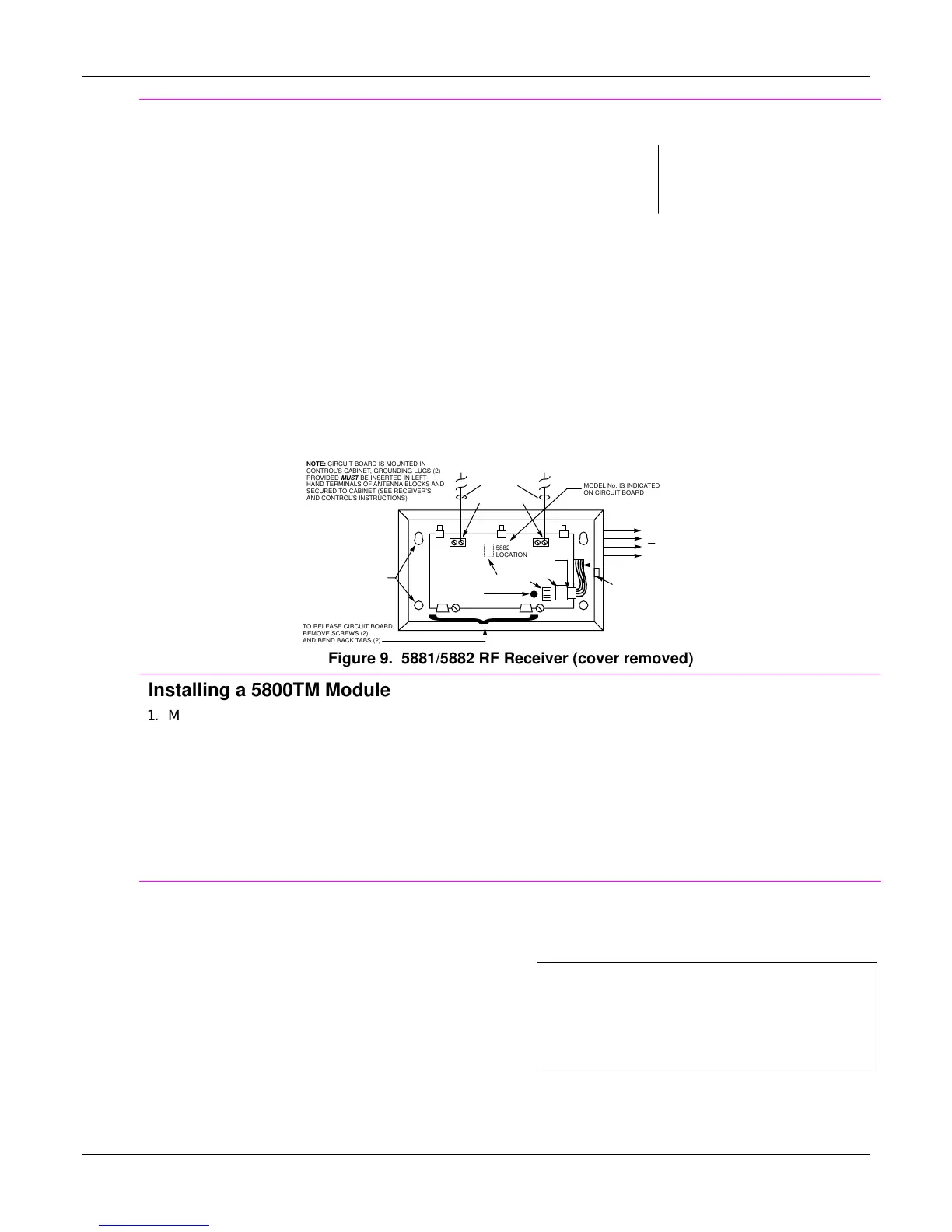
5882
LOCATION
}
TO RELEASE CIRCUIT BOARD,
REMOVE SCREWS (2)
AND BEND BACK TABS (2).
MODEL No. IS INDICATED
ON CIRCUIT BOARD
NOTE: CIRCUIT BOARD IS MOUNTED IN
CONTROL’S CABINET, GROUNDING LUGS (2)
PROVIDED
MUST
BE INSERTED IN LEFT-
HAND TERMINALS OF ANTENNA BLOCKS AND
SECURED TO CABINET (SEE RECEIVER’S
AND CONTROL’S INSTRUCTIONS)
Figure 9. 5881/5882 RF Receiver (cover removed)
Installing a 5800TM Module
1. Mount the 5800TM next to the RF receiver (between
one and two feet from the receiver’s antennas) using
its accompanying mounting bracket. Do not install
within the control cabinet.
2. Connect the 5800TM to the control panel’s touchpad
connection terminals as shown on the Summary of
Connections diagram and set to address 28.
3. For additional information, refer to the 5800TM’s
instructions.
Notes
•
Use this module only if you are using one or
more 5827BD Wireless Bi-directional Touchpads
or 5804BD Transmitters.
•
The 5800TM must be set to address 28 (cut red-
W1 jumper).
Installing the Transmitters
1. To be sure reception of the transmitter's signal at the
proposed mounting location is adequate, perform a
Go/No Go Test, described in the
Testing the System
section.
2. Install transmitters in accordance with the
instructions provided with each.
3. Set 5827, 5827BD, 5804BD transmitters to the
programmed House ID, using its DIP switches.
Notes
•
Refer to the table of compatible devices at the
back of this manual.
U
L
The following transmitters are not intended for use
in UL installations: 5802MN, 5802MN2, 5804,
5804BD, 5814, 5816TEMP, 5819, 5819WHS &
BRS, 5827BD, and 5850.
 Loading...