Safewatch Pro 3000 Installation Instructions
2-10
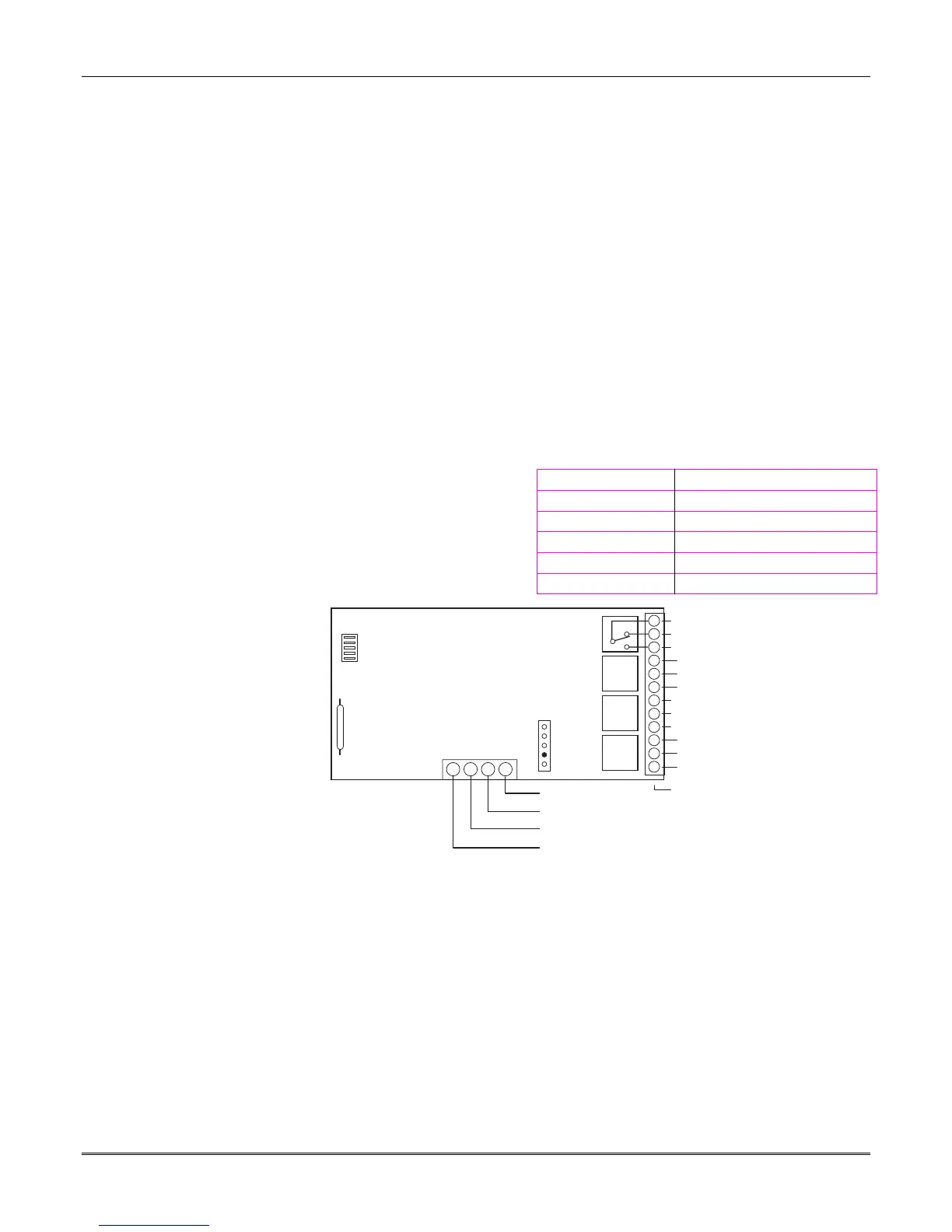
Connecting Relay Modules
1. Mount either remotely or in the control panel.
2. Connect to control’s touchpad terminals using the
connector harness supplied with the module. Use
standard 4-conductor twisted cable for long wiring
runs.
3. Set each module’s device address according to the
table at right.
4. Connect the desired field wiring to the unit's relay
contact terminals.
Notes
•
Use 4204 or 4229 modules.
•
Supervision: 4204 and 4229 modules are
supervised against removal. The module’s device
address is displayed as follows if a module is
disconnected from the control’s terminals, or if
the module cover is removed and the tamper
jumper is installed:
Alpha: CHECK xx Wire Expansion
FAULT xx Wire Expansion
ALARM xx Wire Expansion
Fixed-Glass: lxx (or 91 if field *199 set for 2-digit
display)
where “xx is the module’s address.
•
If communication failure occurs on a device with
zones wired to it, all zones on the device will be
displayed in their respective partitions.
4204 Address 4229 Address
no. 1 12 no. 1 (zn 09-16) 07
no. 2 13 no. 2 (zn 17-24) 08
no. 3 14 no. 3 (zn 25-32) 09
no. 4 15 no. 4 (zn 33-40) 10
no. 5 (zn 41-48) 11
13 14 15 16
C
NC
NO
DIP SWITCH
FOR SETTING DEVICE ADDRESS
AND ENABLING/DISABLING TAMPER
COVER TAMPER (REED) SWITCH
TB1
4204
TB2
4-PIN CONSOLE PLUG
121110987654321
C
NC
NO
C
NC
NO
C
NC
NO
RELAY
3
RELAY
2
RELAY
1
RELAY 4
TYPICAL
(SHOWN "OFF")
EITHER OR BOTH
CAN BE USED
DATA IN
FROM CONTROL
(–) GROUND
DATA OUT
TO CONTROL
(+) 12V
YEL
BLK
GRN
RED
4204
Figure 11. 4204 Connections to Control
(4229 Module is shown in the 4219/4229 Expansion Zones paragraph on page 2-7)
 Loading...