Mounting and Wiring the Control
2-5
Backup Battery
1. Place the 12-volt backup battery in the cabinet.
2. After all connections to the control are completed,
connect the red and black flying leads on the control
board to the battery. Do not attach these leads to the
battery terminals until all connections are completed.
Notes
• Refer to the California State Fire Marshal and
UL Residential Fire requirements statement
below, if applicable.
U
L
Use a 4AH battery or larger for UL
installations.
Earth Ground
Metal Cold Water Pipe:
Use a non-corrosive metal strap (copper is recommended)
firmly secured to the pipe to which the ground lead is
electrically connected and secured.
AC Power Outlet Ground:
Available from 3-prong, 120VAC power outlets only. To
test the integrity of the ground terminal, use a 3-wire
circuit tester with neon lamp indicators, such as the UL
Listed Ideal Model 61-035, or equivalent, available at
most electrical supply stores.
Notes
• This product has been designed and laboratory-
tested to ensure its resistance to damage from
generally expected levels of lightning and
electrical discharge, and does not normally
require an earth ground.
• If an earth ground is desired for additional
protection in areas of severe electrical activity,
terminal 25 on the control board, or the cabinet,
may be used as the ground connection point. The
examples of good earth grounds listed at the left
are available at most installations.
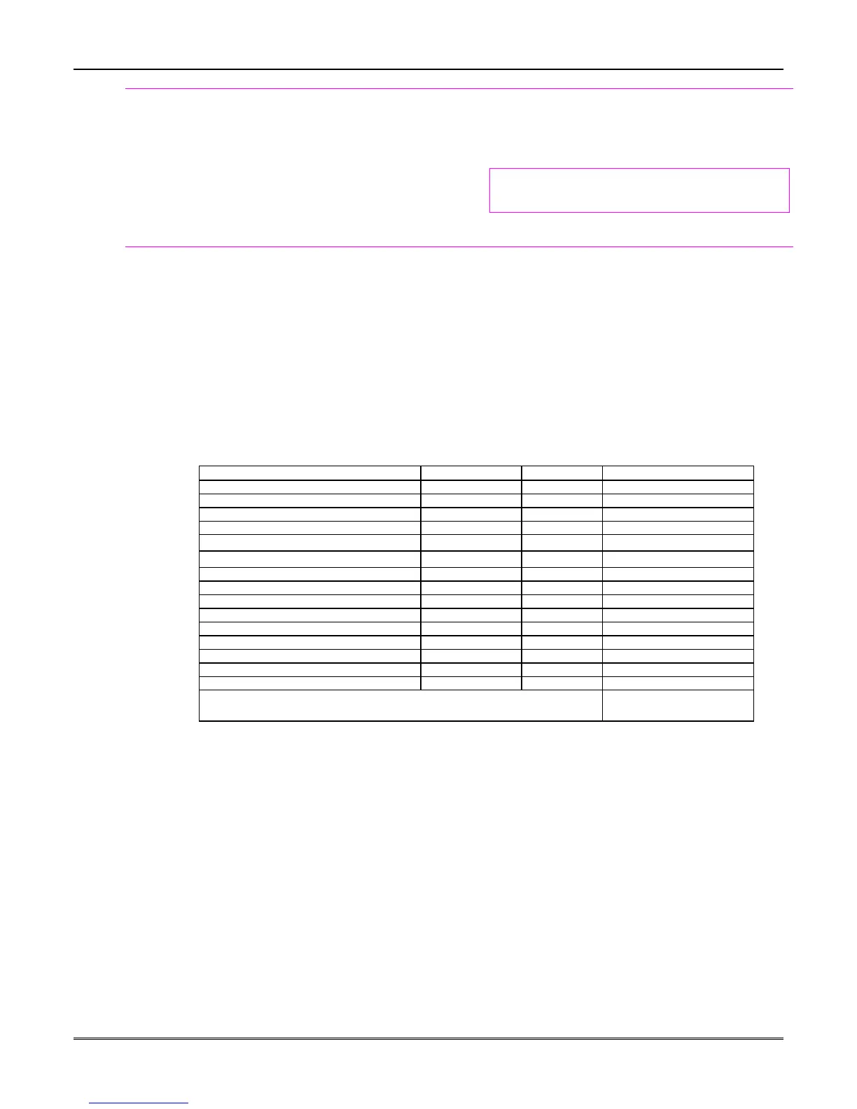
AUXILIARY DEVICE CURRENT DRAW WORKSHEET
DEVICE CURRENT # UNITS TOTAL CURRENT
6137B Touchpad 30 mA
6139B Touchpad 100 mA
5881/5882 RF Receiver 35mA
4219 Zone Expander 35mA
4204 Relay Unit
15/180mA
‡
4229 Zone Expander/Relay Unit
35/100mA
‡
4285 Phone Module 160mA
4286 Phone Module 300mA
*
*
TOTAL =
(Current available from Aux. terminals = 600 mA max.)
†
* If using hardwire devices such as PIRs, refer to the specifications for that particular unit's current draw.
†
In UL installations, maximum current draw from the Auxiliary Output and the Alarm Output
combined
must not
exceed 700 mA (600 mA max from Auxiliary Output).
‡
Figures are for relays OFF/relays ON.
 Loading...