Mounting and Wiring the Control
2-13
Long Range Radio Connections
Connect the data in/data out terminals and voltage
input terminals of the Long Range Radio to the
control's touchpad connection points.
Set the radio’s address to “03” following the
instructions provided with the radio.
Notes
• Use compatible Long Range Radios (e.g.,
7720PLUS, 7820, 7835C, or 7845C).
U
L
For UL installations, Long Range Radio must
be disabled (
∗
29 = 0).
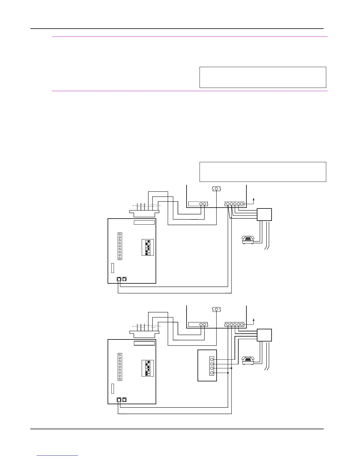
AAV Connections
Refer to the connection diagrams below. One diagram
shows connections when a 4285/4286 Phone Module
is used, the other shows connections when the
4285/4286 is not used.
Connections use the on-board triggers.
Notes
• Suggested AAV Module: Eagle 1250
• When using an AAV unit, you must set field *91
for AAV and program the appropriate output
(output 17 or 18) using *80 Menu mode (select
zone type “60”). E.g., Using output 18 for the
trigger, two output functions in *80 Menu mode
should be:
ZT = 60, P=0, Action = 0, Device = 18;
ZT = 22, P = 0, Action = 2, Device = 18.
U
L
The AAV option cannot be used in UL
installations.
CONTROL / DIALER
HEADER
NOTE:
REFER TO AAV MODULE
INSTRUCTIONS FOR
CONNECTIONS TO AUDIO
SPEAKERS AND MICROPHONE.
•
•
•
•
•
EAGLE
1250
4
5
22
21
23 24
25
DIP Switch
1 2 3 4 5 6
ON
CONTROL
EARTH
GROUND
RED (R)
GREEN (T)
GREY (R)
BROWN (T)
INCOMING
PHONE LINE
TIP
RING
EAGLE
SUPPLIED
CABLE
➤
➤
TO
PREMISES
HANDSET
RJ13X
5
ADT3000-015-V0
(+) EDGE TRIGGER (ORANGE)
GROUND (BROWN)
+12VDC (RED)
TRIGGER
CONNECTOR
OUTPUT 18
Figure 15. Connection of AAV Unit When Not Using a 4285/4286 Phone Module
CONTROL / DIALER
HEADER
NOTE:
REFER TO AAV MODULE
INSTRUCTIONS FOR
CONNECTIONS TO AUDIO
SPEAKERS AND MICROPHONE.
•
•
•
•
•
EAGLE
1250
1
5
22
21
23 24
25
DIP Switch
1 2 3 4 5 6
ON
CONTROL
EARTH
GROUND
RED (R)
GREEN (T)
GREY (R)
BROWN (T)
INCOMING
PHONE LINE
TIP
RING
EAGLE
SUPPLIED
CABLE
➤
➤
TO
PREMISES
HANDSET
RJ13X
2
3
4
4
5
ADT3000-017-V0
(+) EDGE TRIGGER (ORANGE)
GROUND (BROWN)
+12VDC (RED)
TRIGGER
CONNECTOR
OUTPUT 18
4285/4286
Figure 16. Connection of AAV Unit When Using a 4285 or 4286 Phone Module
 Loading...