Safewatch Pro 3000 Installation Instructions
2-4
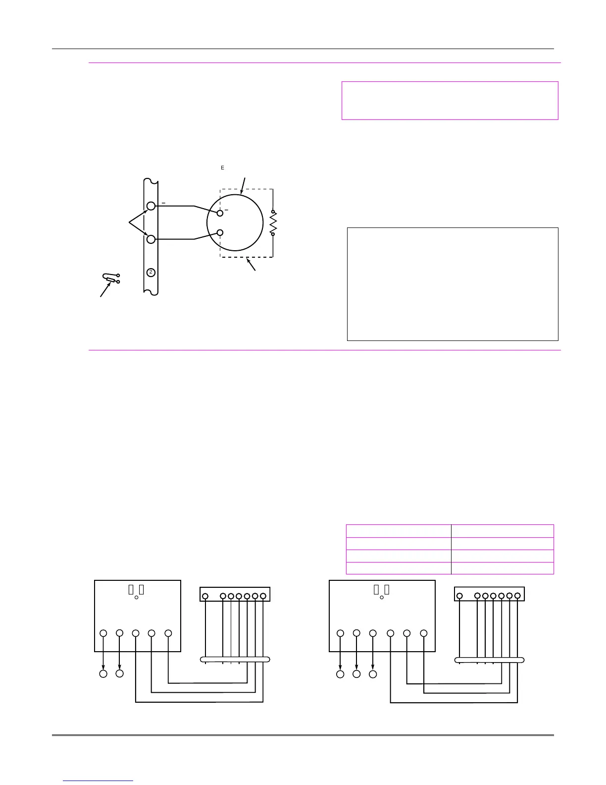
Sounder (Bell) Connections
1. Make sounder connections to alarm output terminals
3 (+) and 4 (–).
For supervised output, continue with steps 2 and 3.
2. Cut the red Bell Supervision Jumper located above
terminals 2 and 3 on the control board.
3. Connect a 2k ohm resistor across the terminals of the
last sounder.
+
+
_
_
2
EXTERNAL ALARM
SOUNDER
TERMINALS ON
CONTROL BOARD
ALARM
OUTPUT
TERMINALS
ADT3000-011-V0
3
4
CUT RED JUMPER ON CONTROL
BOARD TO ENABLE BELL
(SOUNDER) SUPERVISION.
2000
OHM
EOL
RESISTOR
IF BELL SUPERVISION IS ENABLED IN FIELD *91,
AND RED JUMPER ON CONTROL BOARD IS CUT,
CONNECT A 2000 OHM RESISTOR ACROSS THE
EXTERNAL SOUNDER AS SHOWN BY THE
DOTTED LINE.
DO NOT CONNECT THE RESISTOR AT THE
ALARM OUTPUT TERMINALS THEMSELVES!
OBSERVE
POLARITY
Figure 5. Sounder Wiring (Supervised)
Notes
This control complies with NFPA requirements for
temporal pulse sounding of fire notification appliances.
Temporal pulse sounding for a fire alarm consists of:
3 pulses – pause – 3 pulses – pause – 3 pulses–etc..
•
The 12VDC sounder output activates when an
alarm occurs.
•
Total current drawn from this output cannot
exceed 2 amps
(going beyond 2 amps will overload the power
supply, or may cause the electronic circuit
protecting the sounder output to trip).
•
You must install a battery, since the battery
supplies this current.
U
L
•
Use only UL Listed sounding devices for UL
installations.
•
The total current drawn from the alarm output
and the
auxiliary power output, combined,
cannot exceed 700 mA. In addition, the
sounding device must be a UL Listed audible
signal appliance rated to operate in a 10.2-13.8
VDC voltage range, and must be mounted
indoors.
Wiring the AC Transformer
1321 Transformer:
Connect the 1321 Transformer to terminals 1 and 2 on
the control board. See wiring table at right for wire gauge
to use.
4300/1321X10 Transformer
(required if using Powerline Carrier devices)
1. Splice one end of a 3-conductor cable to the wire ends
of the SA4120XM-1 Cable.
2. Connect the SA4120XM-1 cable plug to the 8-pin
connector on the control (see the Summary of
Connections diagram for location of the 8-pin
connector).
3. Connect the other end of the 3-conductor cable to the
4300/1321X10 Transformer, as shown.
Notes
•
Use caution when wiring the transformer to the
control to guard against blowing the transformer
fuse (the fuse is non-replaceable).
•
Wiring to the AC transformer must not exceed
250 feet using 16 gauge wire. The voltage
reading between terminals 1 and 2 of the
control must not fall below 16.5VAC or an “AC
LOSS” message will be displayed.
•
Do not plug the transformer into the AC outlet
while making any wiring connections to the
control. As a safety precaution, always power
down the control when making such connections.
Wiring Table
Distance from control Wire Gauge
Up to 50 feet # 20
50–100 feet # 18
100-250 feet # 16
1345678
4300 TRANSFORMER INTERFACE
TERMINALS ON
CONTROL BOARD
SA412OXM-1
CABLE
1
25
2
EARTH
GROUND
AC AC
AC
SYNC
COM DATA
2
34
5
6
1
2
1
AC
SYNC
COMDATA
23
4
5
1
8-PIN TRIGGER CONNECTOR
KEY
1345678
SA412OXM-1
CABLE
8-PIN TRIGGER CONNECTOR
KEY
CONTROL
BOARD
TERMS.
1321X10 TRANSFORMER
OR
ADT3000-004-V1
+12 AUX.
DATA
COM
SYNC
GND (-)
OUTPUT 17
OUTPUT 18
+12 AUX.
DATA
COM
SYNC
GND (-)
OUTPUT 17
(RED)
OUTPUT 18
(BLUE)
(ORANGE)
(YELLOW)
(BLACK)
(PURPLE)
(GREEN)
(RED)
(BLUE)
(ORANGE)
(YELLOW)
(BLACK)
(PURPLE)
(GREEN)
Figure 6. Connections of 1321X10 and 4300 Transformer to the Control Board
 Loading...