Mounting and Wiring the Control
2-11
Powerline Carrier Devices
1. Install the powerline carrier devices according to the
instructions included with each.
2. Use Programming Mode to enter the device house ID
in data field*27, and enter the unit code using *79
Output Device menu Mode.
See connections diagram in the AC Wiring paragraph for
connecting the 4300/1321X10 transformer.
Notes
• When using Powerline Carrier devices, you must
use a 4300 or 1321X10 Transformer instead of
the 1321 Transformer.
• The 4300/1321X10 Transformer provides AC
power to the control panel, and also supplies
signals from the control panel through the
premises AC wiring to the Powerline Carrier
devices (which are plugged into AC outlets). You
can then make devices that are plugged into
Powerline Carrier devices perform various
functions in response to commands you enter at
the security system touchpads.
U
L
Powerline Carrier devices and the 4300
Transformer are not UL Listed for fire or burglary
functions and are intended for home automation.
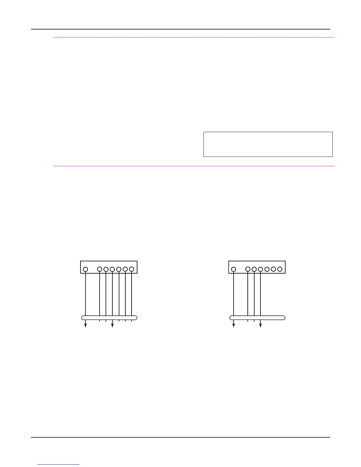
On-Board Triggers
Connect field wiring to the desired trigger pin on the
8-pin trigger connector centrally located above the
terminal strip.
• If using 1321X10 transformer and powerline
carrier devices, use the SA4120XM-1 cable.
• If only using the on-board triggers, you can use a
standard touchpad cable as shown below.
Notes
• There are two on-board triggers that can be
used to activate output devices.
• Program these triggers using *80/*81 Menu
modes as you would for any other relay output.
• When programming these outputs, note:
pin 1 = output number 17 (trigger 1):
56 ohms to ground when closed;
open when off
pin 5 = output number 18 (trigger 2):
100 ohms to ground when closed;
open when off
1345678
SA412OXM-1
CABLE
8-PIN TRIGGER CONNECTOR
KEY
ADT3000-006-V0
+12 AUX.
DATA
COM
SYNC
GND (-)
OUTPUT 17
(RED)
OUTPUT 18
(GREEN)
(ORANGE)
(YELLOW)
(BLUE)
(PURPLE)
(BLACK)
1345678
STANDARD
TOUCHPAD
CABLE
8-PIN TRIGGER CONNECTOR
KEY
ADT3000-016-V0
+12 AUX.
GND (-)
OUTPUT 17
OUTPUT 18
(RED)
(YELLOW)
(BLACK)
(GREEN)
Figure 12. On-Board Trigger Connector with Figure 13. On-Board Trigger Connector with
SA4120XM-1 Cable for Use With 1321X10 Transformer Standard Touchpad Cable for Trigger Use Only
 Loading...