Safewatch Pro 3000 Installation Instructions
6-2
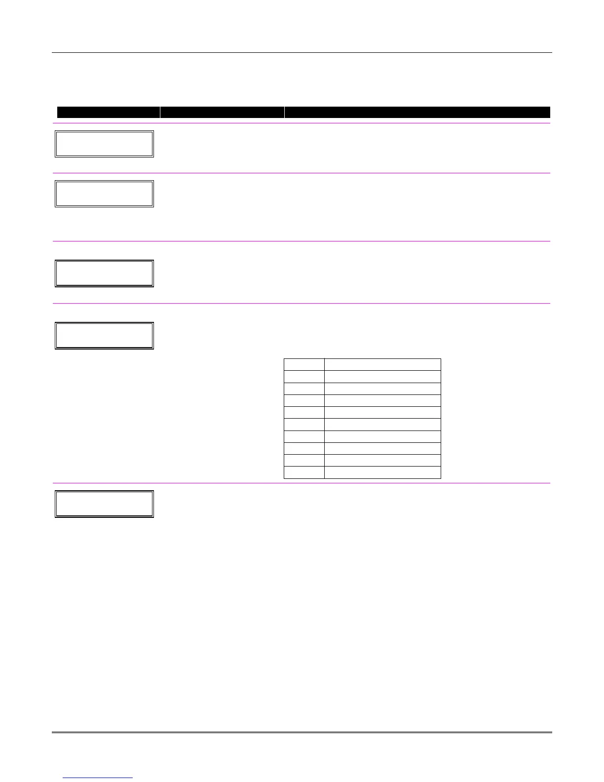
Start Output Device Mapping by pressing *79 while in Data Programming Mode. The following
prompts are displayed:
∗79 Menu Mode
PROMPT VALID ENTRIES EXPLANATION
ENTER OUTPUT NO.
00 = QUIT xx
Device Output Number
01-18
[
∗
] to continue
This is the logical (or reference) relay number as used in the system.
Relays and X-10 devices are numbered 01-16; the on-board triggers
are numbered 17 and 18. Use the worksheet on the Programming
Form (printed separately) to organize device numbers.
XX OUTPUT TYPE
0 = rly, 1 = X10 0
Output Type
0 = delete
1 = relay on 4204/4229 module
2 = Powerline Carrier device
[
∗
] to continue
Select whether this is a relay or a Powerline Carrier (X-10) device.
If X-10 is selected, go to “A” prompt.
If relay is selected, skip to “B” prompt.
“A”
XX UNIT No.
yy
Unit Number
01-15 = predefined address
[
∗
] to continue
If X-10 is selected, a prompt for the unit number appears.
Enter the unit code (set at the device) and press [
∗
].
The system returns to the Device Number prompt.
“B”
XX MODULE ADDR
07-15 yy
Module Address
07-15 = predefined address
[
∗
] to continue
If relay is selected, this prompt appears.
Enter the predefined address for this module as listed below. Make
sure the module’s DIP switches are set to the selected address.
Address Module
07 1st 4229 (with zones 09-16)
08 2nd 4229 (with zones 17-24)
09 3rd 4229 (with zones 25-32)
10 4th 4229 (with zones 33-40)
11 5th 4229 (with zones 41-48)
12 1st 4204
13 2nd 4204
14 3rd 4204
15 4th 4204
XX REL POSITION
1-4 zz
Relay Position
[
∗
] to continue
This is the actual (or physical) relay number with respect to the
Relay Module upon which it is located. For 4204 modules, relay
numbers are 1-4. For 4229 modules, relay numbers are 1-2.
The system returns to the Device Number prompt for programming
the next device.
 Loading...