ADT-CNC46XX 系列维护手册
- 76 -
12.
Hardware interface definition and connection instructions
12.1 Installation layout
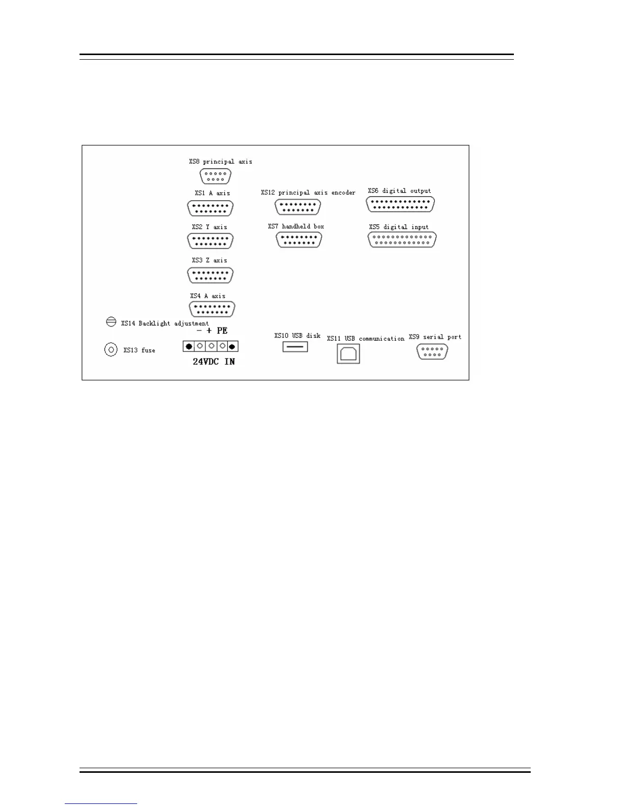
12.1.1 External interface diagram
⑴ X axis, Y axis, Z axis, A axis:
15-core D-pin socket connects to step motor drive or digital AC servo drive
⑵ XS5 digital input:
25-core D-pin socket inputs signals for every axis limit and other switching quantity
⑶ XS6 digital output:
25-core D-pin socket outputs signals for switching quantity
⑷ USB and serial port exchange files between PC and CNC4640 controller and realize other functions.
⑸ CNC4640 controller uses 24V DC power supply, and the internal power consumption is about 5W.
⑹ XS7 accessory panel:
15-core D-pin socket connects to handwheel
⑺ XS8 principal axis:
9-core D-pin socket connects to principal axis inverter