Adtech CNC Technology Co., Ltd. 12. Hardware interface definition and connection instructions
- 89 -
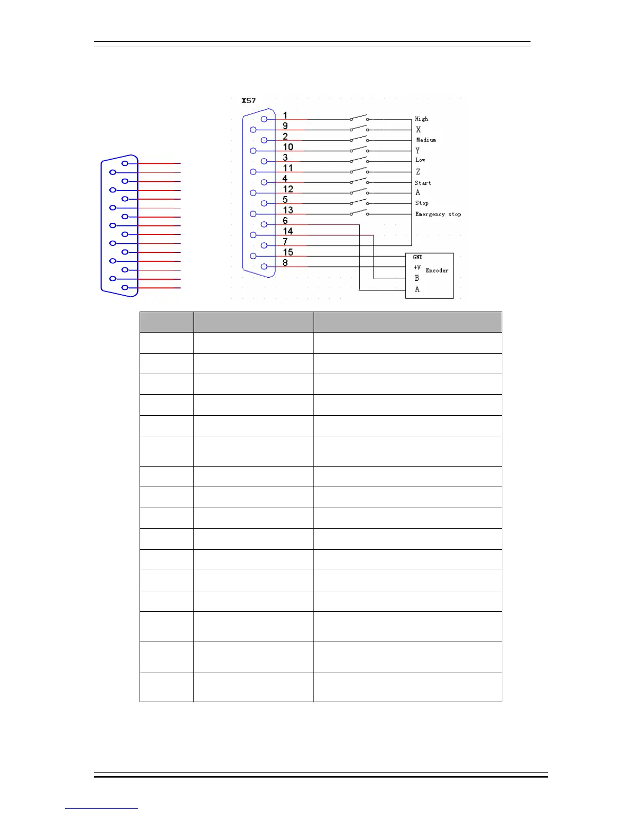
12.2.4 Handheld box interface (XS7)
HA
IN33
8
15
7
14
6
13
5
12
4
11
3
10
2
9
1
5V+
IN32
IN31
HB
24V-
IN28
IN26
IN25
IN24
IN29
IN30
IN27
5V-
Wire No. Definition Function
1 (IN24) gear switch 0.1 gear --- High speed
2 (IN26) gear switch 0.01 gear --- Medium speed
3 (IN28) gear switch 0.001 gear --- Low speed
4 (IN30) button Cycle start
5 (IN32) button Emergency stop
7 24V-
Negative pole of internally provided 24V
power supply
9 (IN25) axis selection X axis
10 (IN27) axis selection Y axis
11 (IN29) axis selection Z axis
12 (IN31) axis selection A axis
13 (IN33) button Emergency stop
6 HA Hand encoder phase A input signal
14 HB Hand encoder phase B input signal
15 5V-
Negative pole of internally provided 5V
power supply
8 +5V
Positive pole of internally provided 5V
power supply
7 24V-
Negative pole of internally provided 24V
power supply