Adtech CNC Technology Co., Ltd. 12. Hardware interface definition and connection instructions
- 91 -
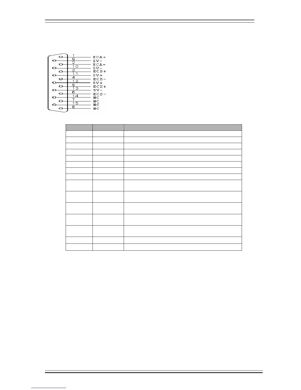
12.2.6 Principal axis encoder interface (XS12)
Principal axis encoder wiring diagram:
This wiring is suitable for 4640/4620 controller
Wire No. Definition Function
1 ECA+ Encoder phase A input +
2 ECA- Encoder phase A input -
3 ECB+ Encoder phase B input +
4 ECB- Encoder phase B input -
5 ECZ+ Encoder phase Z input + (standby)
6 ECZ- Encoder phase Z input - (standby)
7 NC Null
8 NC Null
9 5V-
Negative end of internal 5V power supply; can’t be
connected to external power supply
10 5V-
Negative end of internal 5V power supply; can’t be
connected to external power supply
11 5V+
Positive end of internal 5V power supply; can’t be
connected to external power supply
12 5V+
Positive end of internal 5V power supply; can’t be
connected to external power supply
13 5V-
Negative end of internal 5V power supply; can’t be
connected to external power supply
14 NC Null
15 NC Null
¾ AB phase decoder input allows differential connection and common anode connection, which will be determined by the
encoder type.
¾ Encoder output modes include open collector, complementary, voltage and long drive, among which open collector,
complementary and voltage output use common anode connection, and long drive output uses differential connection.
¾ As shown in the figure below, AB phase decoder input signal uses differential input connection; if common anode
connection is used, the positive ends of phase A and phase B must be connected; for common cathode connection, the
negative ends of phase A and phase B must be connected.