Adtech CNC Technology Co., Ltd. 12. Hardware interface definition and connection instructions
- 81 -
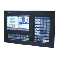
Wire No. Definition Function
1 PU+ Pulse signal +
2 PU- Pulse signal -
3 DR+ Direction signal +
4 DR- Direction signal -
5 ALM
Servo alarm signal input
X axis: IN34, Y axis: IN35, Z axis: IN36, A axis: IN37
6 OUT
Axis alarm reset output signal
X axis: OUT24, Y axis: OUT25, Z axis: OUT26 A, axis:
OUT27
7 ECZ+ Encoder phase Z input +
8 ECZ- Encoder phase Z input -
9 PUCOM Controller for single end input
10 24V+
11 24V-
Internally provided 24V power supply, directly connected to
24V power supply of the controller
12 ECA+ Encoder phase A input +
13 ECA- Encoder phase A input -
14 ECB+ Encoder phase B input +
15 ECB- Encoder phase B input -
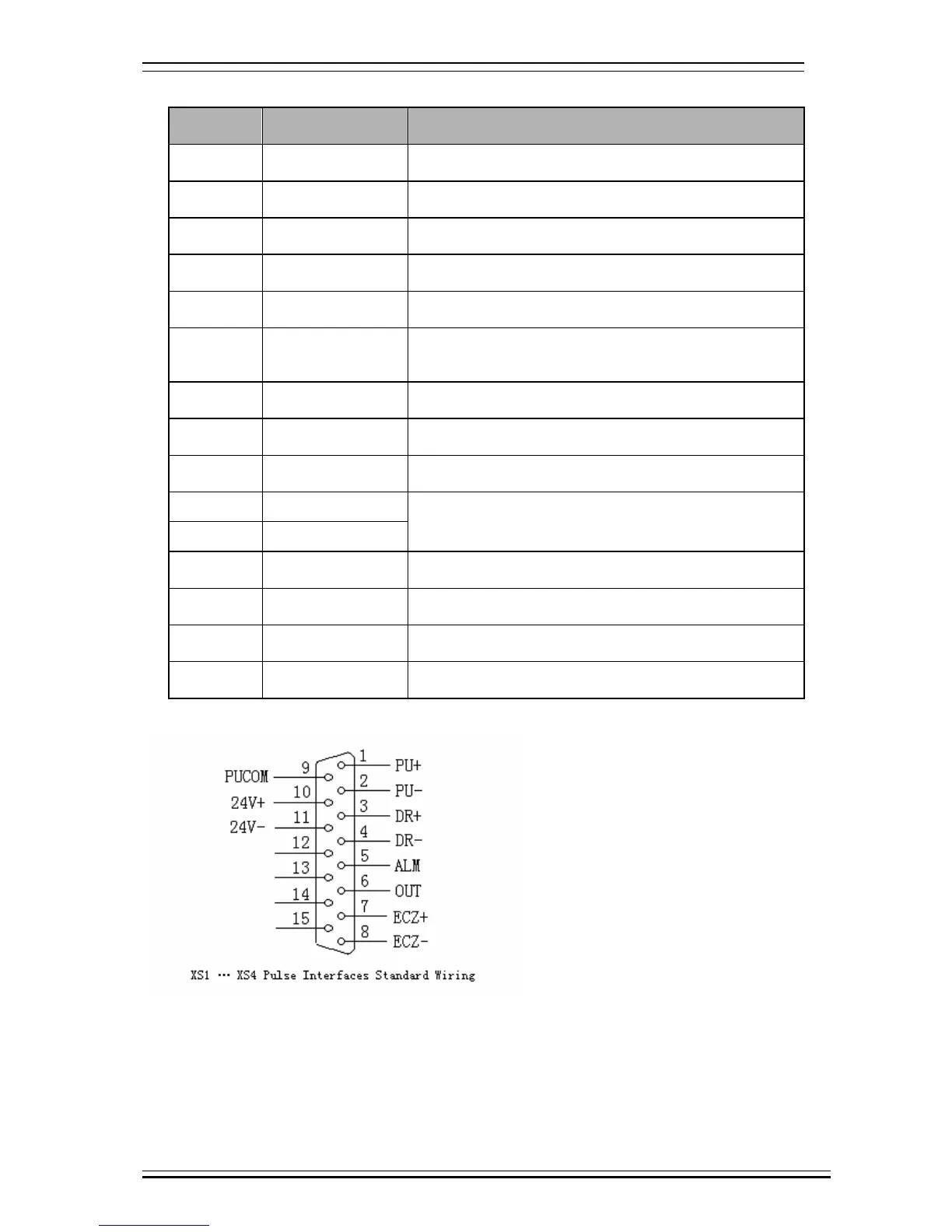
Standard pulse wiring diagram
This wiring is suitable for CNC4640/4620/4340/4240/4342 controller;
Step motor drive cable to differential input
Adtech CNC drive is for reference, all of which use differential input mode. This mode has strong
anti-interference and is recommended. Please refer to the figure below for the connection of CNC with step
motor drive and step motor