OsmoPRO MAX Automated Osmometer User Guide
68
9.1 The Diagnostics Menu
Use the Diagnostics menu to check the performance of
dierence instrument components.
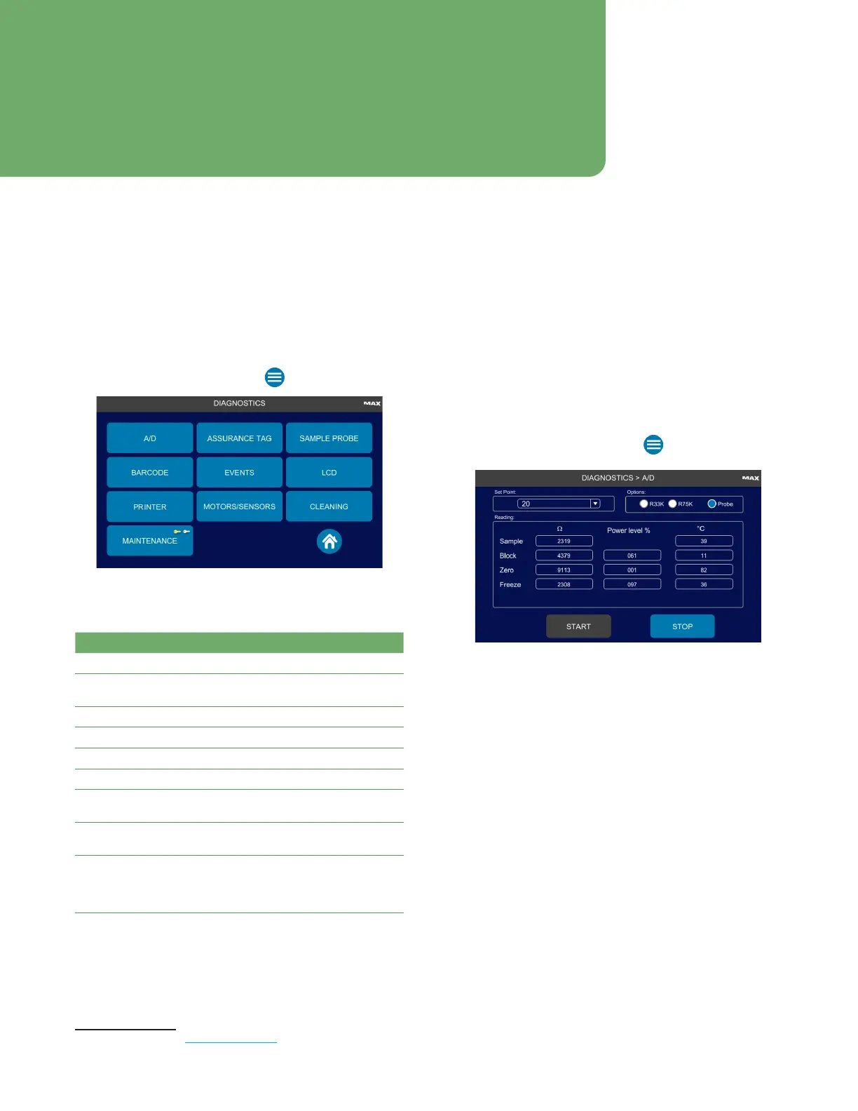
1. From the Home screen, press > Diagnostics.
2. Select one of the following diagnostics functions:
Function Description/Use
A/D Analog-to-digital circuit testing
Assurance Tag Test scanning an assurance on the
assurance tag readers
Sample Probe Measure the sample probe resistance
Barcode Test the barcode scanner
LCD Inspect screen for dead pixels
Printer Test the printer
Motors/
Sensors
1
Test instrument motors and sensors
Cleaning
1
Supervisors can log fluidics cleaning and
pipettor priming.
Maintenance Supervisors can perform and log routine
cleaning, preventative maintenance, and
repairs of the instrument, and save to the
events database.
1 This function is covered in Instrument Maintenance.
9.2 Testing the Analog-to-Digital Converter
Use the A/D feature to test the analog-to-digital
converter (A/D), sample probe, block probe, cooling
assembly, and the eciency of heat transfer between the
cooling assembly components. Results are presented as
resistance (ohms), temperature (°C), and power
level(%).
1. From the Home screen, press Diagnostics > A/D.
2. Select the Probe option.
3. Select a Set Point temperature to adjust the
temperature for the cooling assembly (sample block,
freeze block, and cold block).
4. Press Start.
After five minutes, the block temperature should
roughly equal the set point temperature.
NOTE: Power level is expressed as a percentage,
indicating how much power the thermoelectric
cooler uses to reach a temperature set point
sensed by the block probe. An increasing
power-level requirement indicates deteriorating
performance of the cooling assembly.
Chapter 9: Diagnostics