4.16 Brake Gap Adjustment
Once the brake is adjusted (at the factory), it should not require adjustment. But, if the brake is
not functioning properly, adjustment may be required.
To check the brake gap, turn the power to the OFF position, disconnect air and remove the left
panel cover. Using a .014 Feeler Gauge, insert the gauge between the outer plate and the second
plate. If the gauge is "snug", the gap is properly set.
If the gauge is too loose or cannot be inserted between the plates, loosen the two set screws
located on the brake collar (Fig. 4-24). Place the Feeler Gauge between the plates and press the
outer plate against the feeler gauge. Press the brake collar against the outer plate and tighten the
set screws. Replace the left cover, plug in the power cord, connect the air line and turn the main
power to the ON position.
4.17 Battery Replacement .
The T-1000 has a backup battery located on the PLC
board. Battery Types: PLC Battery - Model No.
AFB8801. Lithium Battery, BR2032/CR2032 type or
equivalent.
The life of the battery is 53,000 hours (approx. 6 years).
The battery stores current configuration settings of the
program. When jobs are no longer being saved in the
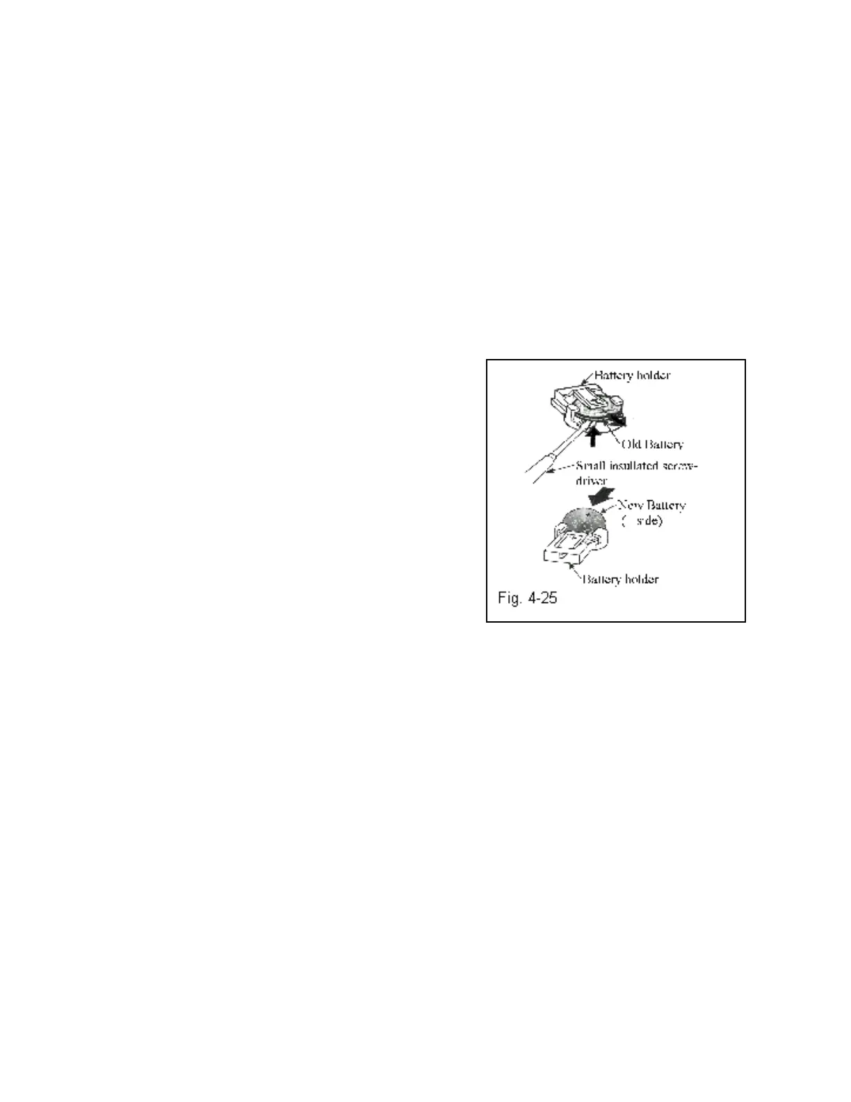
PLC, replace the battery. To replace the battery from the
PLC remove the left cover and PLC plastic cover.
Remove the battery as illustrated on Figure 4-25, using a
small insulated screw driver, with the positive side (+)
facing you.
When replacing the battery, you will not lose settings if a new battery is replaced within 3
minutes after the low battery has been removed.
CAUTION: If you fail to use insulated tools, they may cause a short-circuit between the
battery and the equipment.
4.18 PLC EPROM Installation Instructions
For IOP Version T-1000
Note: Please read the following instructions carefully to prevent damage to components and
avoid loss of data.
1. Ensure the T-1000 power is turned OFF.
2. Remove the right side (as you are facing the front of the T-1000) cover by first removing the
bolt then pulling the cover outwards on bottom and then lifting upwards to remove.
3. The PLC is located towards the back top portion of the right panel.
Pull back the plastic cover on the PLC without removing.
4. The EPROM is located on the top left side of the PLC.
Refer to Fig. 4-8 of the T-1000 manual (User memory socket).
70