Installation
Item Specification
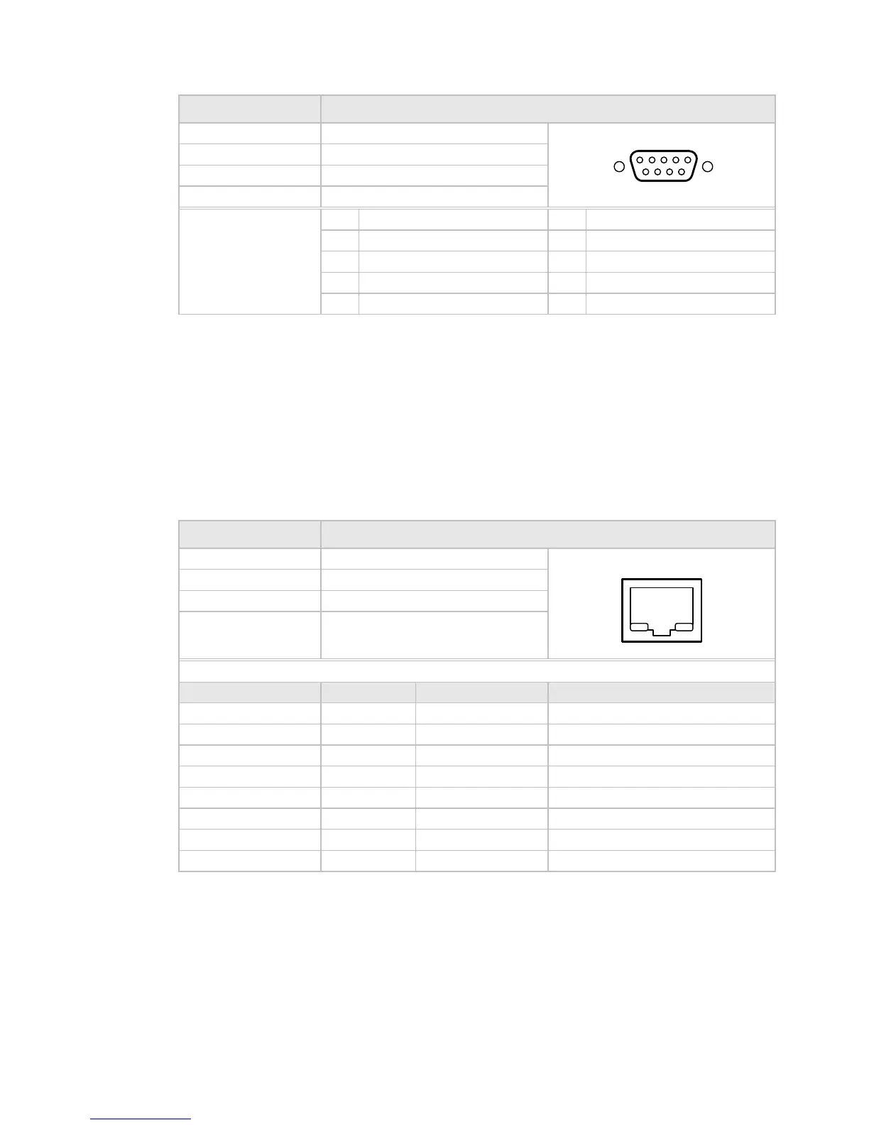
Connector type: 9-way, D-type, Female
Connector designation: M&C RS485
Standard: RS485
Configuration: DCE
Pin-outs: 1 Signal Ground 6 Power Detector +
2 Power Detector 7 Not Used
3 Not Used 8 RS-485 Rx+
4 RS-485 Tx+ 9 RS-485 Rx-
5 RS-485 Tx-
1 5
6 9
2.6.3 M&C Connector - 10/100BaseT Ethernet
There are two 10/100BaseT Ethernet M&C ports on the rear panel. One is labeled ETHERNET, and
the other is labelled M&C DEMOD (both are RJ-45 connectors; see Table 2.7 for pin-outs). The
M&C DEMOD connector is used during manufacturing and upgrades, and relates to the
demodulator (if fitted) only, and should not be used in the field. The ETHERNET connector
provides Ethernet capabilities for all functions of the modulator, including the modulator,
demodulator, and interface cards (if fitted).
Table 2.6: M&C Connector - 10/100BaseT Ethernet
Item Specification
Connector type: RJ-45 socket
Connector designation: ETHERNET
Standard: 10/100BaseT
Configuration: -
Pin-outs:
RJ-45 Pin Number Description Wire Color Codes Crossover Cable Pins
1 TX + White W/Orange 3
2 TX - Orange 6
3 RX + White W/Green 1
4 Blue
5 White W/Blue
6 RX - Green 2
7 White W/Brown
8 Brown
1 8
2.6.4 Monitor and Control Alarms
The connector labelled P5, a 15-pin D-sub (F) provides Form C relay outputs of the modulator’s
status. Refer to Table 2.8 for pin-outs and signal description.
Table 2.7: Alarm Connector Pin-outs
2-10 SBD75e Series Modulator Installation and Operation Manual
 Loading...