Installation
2.6.6 RF (L-Band) Output Connector
The connector labelled as L-Band OUT transmits RF signals to the antenna. For signal
specification, see Appendix A: Technical Specification.
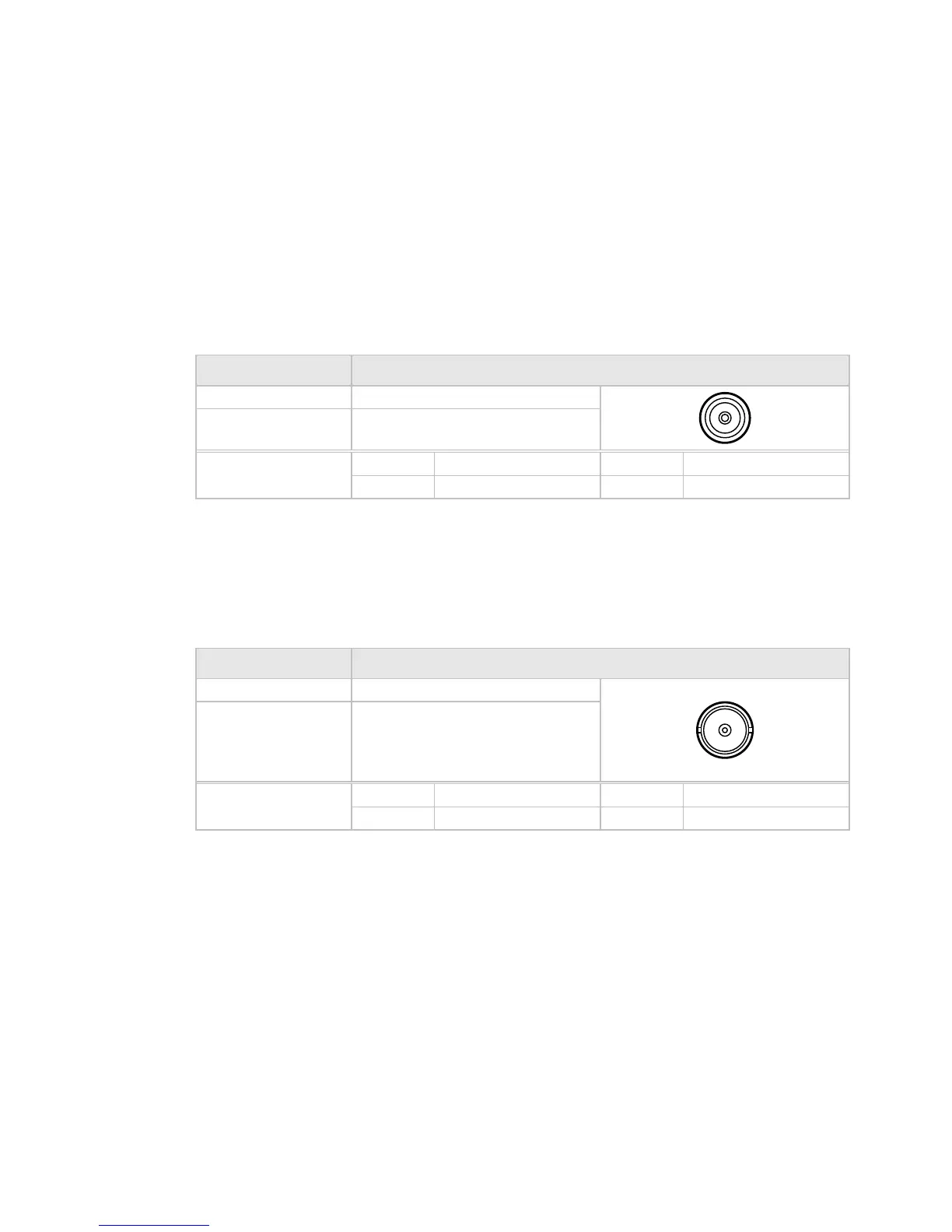
Table 2.9: RF (L-Band) Output Connector
Item Specification
Connector type: F-type 50 Ω female socket
Connector designation: L-BAND OUTPUT
Pin-outs: Centre RF Signal
Shield Ground/Chassis
2.6.7 ASI Input Connector
One or more ASI inputs may be provided on the rear panel, labelled as ASI 1, ASI 2, etc., to
receive transport streams. For signal specification, see Appendix A: Technical Specification.
Table 2.10: ASI Input Connector
Item Specification
Connector type: BNC 50 Ω socket
Connector designation: ASI IN 1
ASI IN 2
ASI IN 3
ASI IN 4
Pin-outs: Centre Video Signal
Shield Ground/Chassis
2.6.8 1Pulse Per Second (1PPS) InputConnector
One connector is provided to receive a 1PPS signal reference. For signal specification, see
Appendix A: Technical Specification.
2-12 SBD75e Series Modulator Installation and Operation Manual
 Loading...