Installation
Item Specification
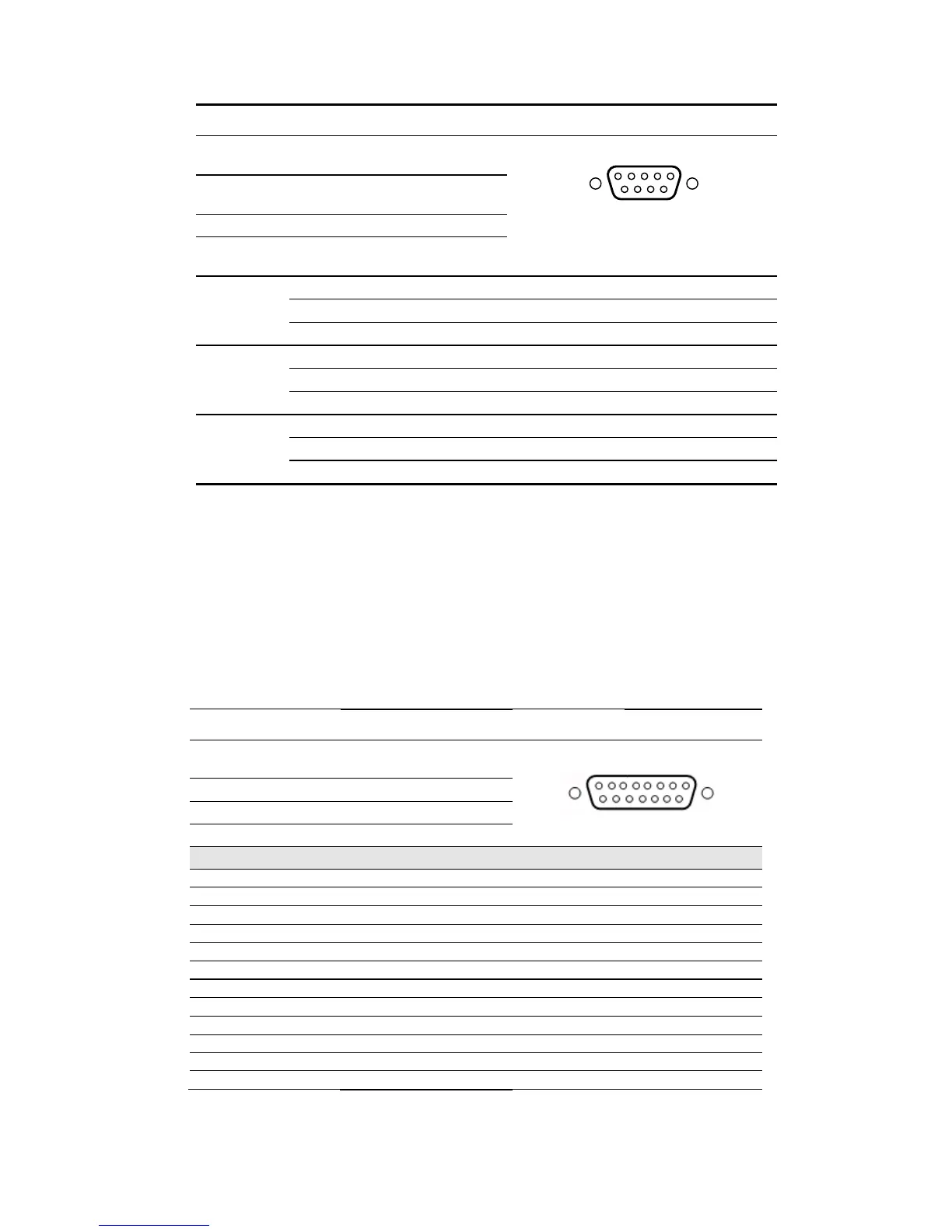
Connector
type:
9-way, D-sub type, Female
Connector
designation:
ALARMS
Standard: Custom
Configuratio
n:
-
Relay 1: Not
Ued
1 Common
6 Normally Open
8 Normally Closed
Relay 2:
Modulator
2 Common
7 Normally Open
3 Normally Closed
Relay 3: Not
Used
5 Common
4 Normally open
9 Normally closed
1
5
6
9
2.6.5 Redundancy
This is an optional feature, although the connector appears on the rear panel (REDUNDANCY, a
15-pin D-sub female). A redundancy kit can be purchased from Advantech AMT to allow two
modulators to be connected in a 1:1 redundancy configuration.
Table 2.8: Redundancy Connector Pin-outs
Item Specification
Connector type:
9-way, D-sub type,
Female
Connector designation: ALARMS
Standard: Custom
Configuration: -
DB15 (A) DB15 (B) RF SWITCH Note
1 2 AV1 RF SW Drive, unit A
2 1 AV2 RF SW Drive, unit B
3 3 COM Signal Ground
6 14 -- Future Use
7 13 -- Future Use
8 15 -- B --> A Redundancy
9 9 +C RF SW +12V
11 12 1 RF Relay O/P NC
12 11 2 RF Relay O/P NO
13 7 -- Future Use
14 6 -- Future Use
15 8 -- A --> B Redundancy
SBD75e Series Modulator Installation and Operation Manual
2-11
 Loading...