Installation
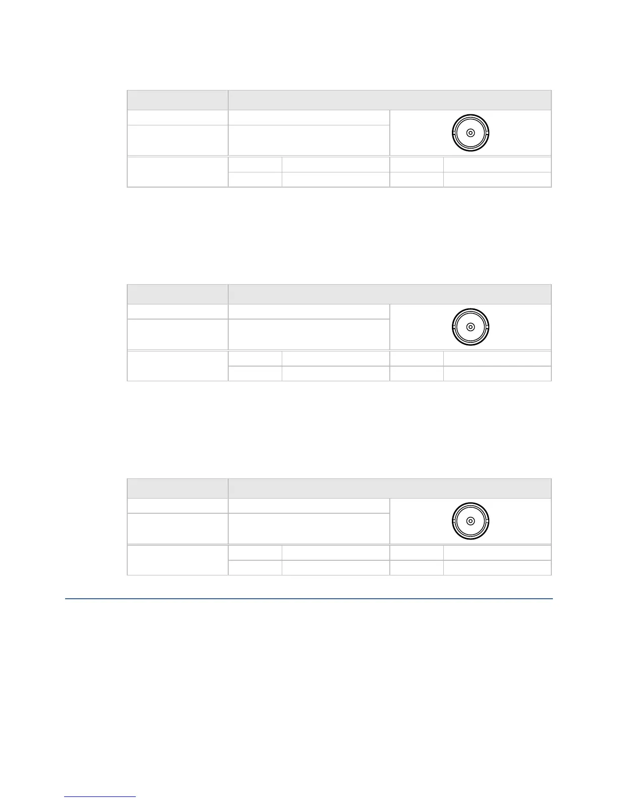
Table 2.11: 1PPS Input Connector
Item Specification
Connector type: BNC 50 Ω socket
Connector designation: 1PPS IN
Pin-outs: Centre Video Signal
Shield Ground/Chassis
2.6.9 External Reference Input Connector
One connector is provided to receive an external reference signal. For signal specification, see
Appendix A: Technical Specification.
Table 2.12: Ext Ref In Connector
Item Specification
Connector type: BNC 50 Ω socket
Connector designation: EXT_REF_IN
Pin-outs: Centre Video Signal
Shield Ground/Chassis
2.6.10 70/140 MHz (IF) Output Connector
One IF output connector provides an IF output. For signal specification, see Appendix A:
Technical Specification.
Table 2.13: 70/140 MHz (IF) Output Connector
Item Specification
Connector type: BNC 50 Ω socket
Connector designation: 70/140 MHz OUT
Pin-outs: Centre Video Signal
Shield Ground/Chassis
2.7 Configuring the Modulator for Best Performance
2.7.1 Bringing the Modulator Online
When bringing a transmit carrier on line, the following sequence must be followed:
1. Power on the modulator for five minutes to allow the oscillator to stabilize.
2. Before connecting the L-band cable to the BUC, verify that:
The Symbol rate and the frequency of the modulator are correctly set
SBD75e Series Modulator Installation and Operation Manual
2-13
 Loading...