32
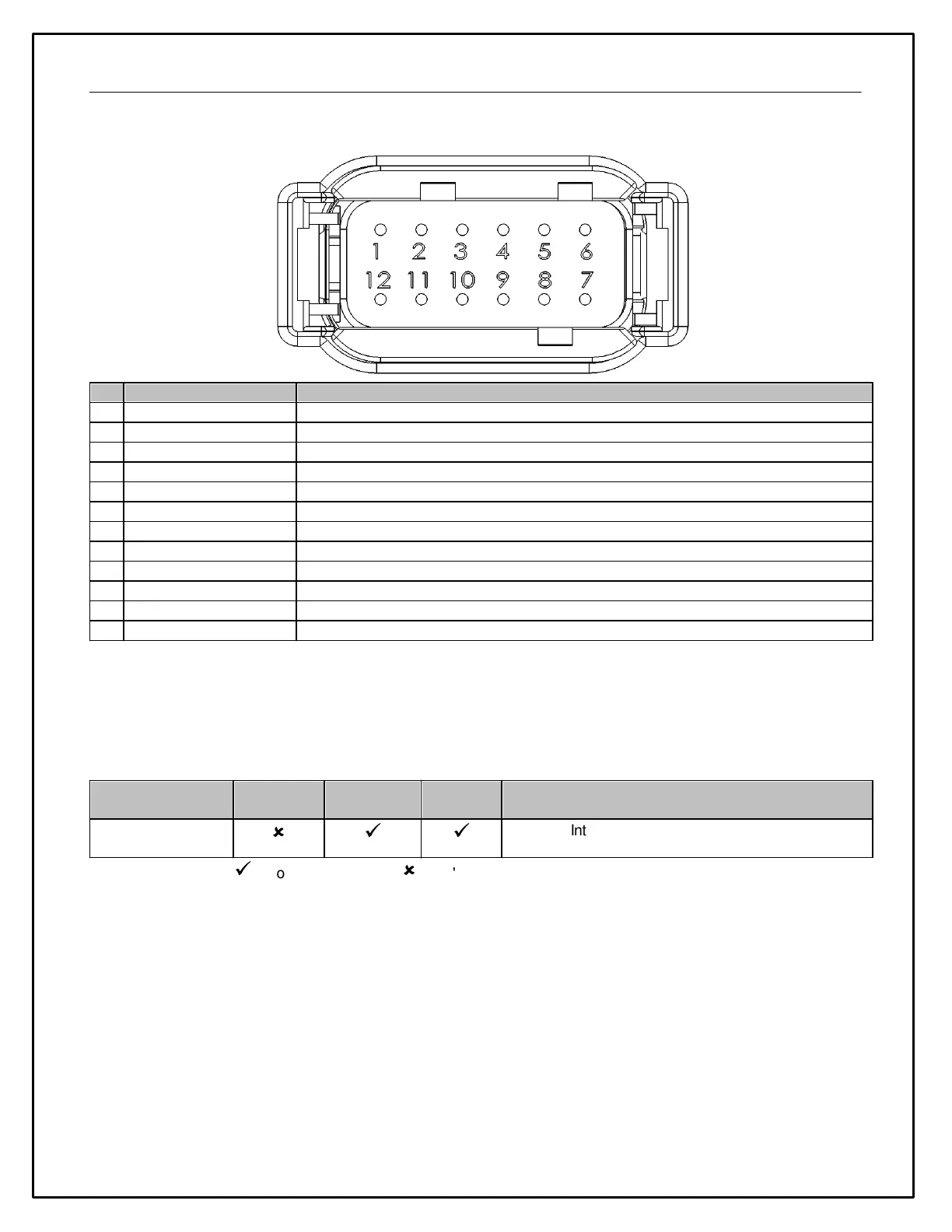
Device Pinout
Primary ignition/battery power input
Primary ignition/battery ground input
Temperature / thermistor input, 2200 Ohm 5V pull-up
Temperature / thermistor input, 2200 Ohm 5V pull-up
0-5V Analog input, 100k Ohm 5V pull-up
0-5V Analog input, 100k Ohm 5V pull-up
Engine speed input (negative coil terminal) 12V pull-up
0 - 250 Ohm fuel level sensor input
5V sensor reference power output
Analog Inputs 1 - 2
These inputs have a 2200 Ohm 5V pull-up resistor and are suitable for two-wire thermistor temperature sensors. It is
not recommended to connect these inputs to pre-existing/OEM sensors that are already connected to a factory ECU
or logging device. Please refer to the table below for connection examples.
Intake, coolant/oil temperature, etc
ü
= Connect
û
=Don't connect ! = Read Notes
CAN Output
The measured resistance will be output via CAN and will have to be scaled to temperature in the receiving device. A
thermistor's resistance varies non-linearly with temperature and thus the receiving device will likely require a look-up
table to properly log or display temperature. The AEM CD series of dashes have this capability; please refer to the
appropriate documentation.