46
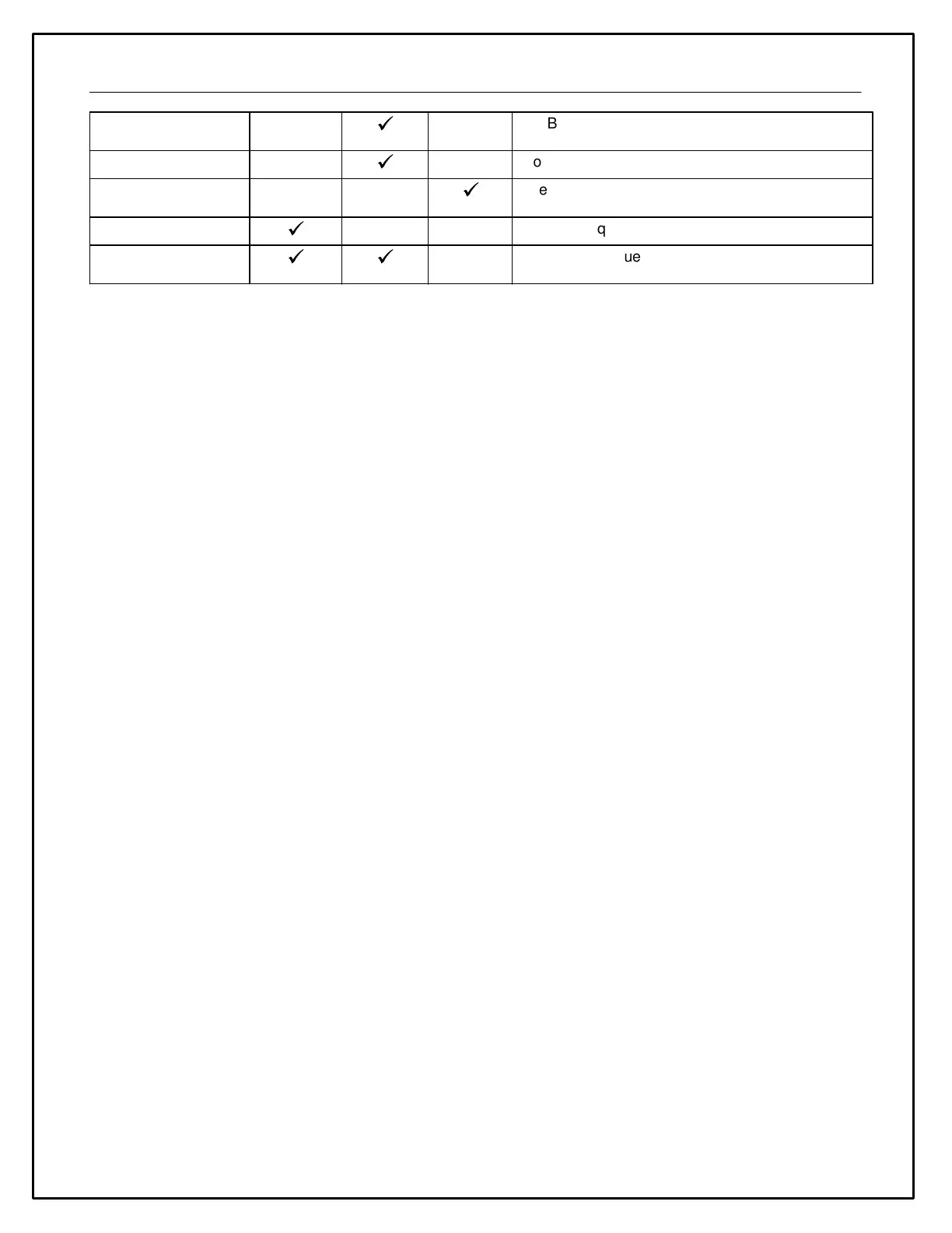
Boost solenoid duty cycle is proportional to
boost/MAP
Solenoid duty cycle is proportional to line pressure
Clutch Switch / Trans
Brake*
The output will change to '1' or 'ON' when grounded
Frequency is proportional to airflow
Frequency = Ethanol Content
Duty Cycle = Fuel Temperature
* Duty Cycle and State are active low inputs ** The Sensor Module does support OEM ECU multi-pulse signals
Note: These inputs are flyback protected but only suitable for low-energy signals. Do not connect these inputs to
ignition coils or VR sensors. Please refer to the device specifications further in this manual.
CAN Output
Each input will output the following three parameters:
Frequency (Hz) - The reciprocal of the period of a signal where the period is the amount of time between two rising
(or falling) edges.
Duty Cycle (%) [Active Low] - The fraction of one period in which the signal is low.
State [Active Low] - This output will be "1" or "ON" when the input is grounded and "0" or "OFF" when disconnected
or above the threshold voltage of ~7.5V. Note that this output is de-bounced and not suitable for fast changing
signals (> ~1Hz). It is best suited for mechanical driver-operated switches with two positions.
Jumper Configuration
Several configuration jumpers are located beneath the rear cover of the Sensor Module. The rear cover may be
removed by unscrewing the four external screws to change the jumper positions if needed. The Sensor Module is
delivered from the factory in the most common configuration suitable for use with AEMnet (and other) devices;
changing the jumper positions is not typically necessary.
CAN TERM - A maximum of two termination resistors should be active per CAN bus installation. Please refer to the
documentation for the other devices on your network.
VR SENSE - The default/recommended position is "HI" which should work well for most situations. The "LOW"
setting may be tried if there are low-speed signal dropouts.
ANx PULLUP - Please refer to the 'Analog Inputs 5 - 8' section of this manual.
CAN SPEED - The default position of 500k is correct for AEMnet. Please refer to the manufacturer's documentation
if you are using any third-party devices.
CAN BITS - The default position of 29 is correct for AEMnet. Please refer to the manufacturer's documentation if
you are using any third-party devices.
CAN ID - The default position of 1 is correct if there is only a single AEM CAN Sensor Module installed on your
network. If you are using two Sensor Modules, the first unit must be set to '1' and the second to '2'. The second
Sensor Module on a network with two modules will transmit at half the rate of the first to prevent overloading the bus.