40
Electrical
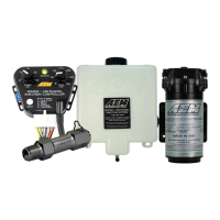
The supplied 36-2212 harness comes with a pre-terminated AEMnet spur suitable for powering the module and
providing AEMnet/CAN connectivity. In addition, pre-terminated lengths of various color wire are supplied for
connection to sensors. The harness connector is a multi-piece assembly which has a clear plastic retainer that
must be removed prior to inserting the crimped leads into the assembly. Please see instructions later in this
manual.
Sensor Wiring
·
The Sensor Module should only be powered through the dedicated power and power ground pins, *not* sensor
ground
·
Every connected sensor should be connected to one of the dedicated sensor ground pins to ensure accurate
readings
·
Do not connect the Module's 5V sensor power to anything other than dedicated sensors that require 5V power,
e.g. pressure sensors
·
Route wiring away from sources of noise such as alternators, ignition components, or other high power/frequency
wiring
·
Shielded wire is suggested to reduce the susceptibility of noise; the shield should only be grounded/drained on
one end of the wiring harness
·
CAN wiring should utilized twisted pairs (> 1 TPI); shielding is recommended
·
This module is not compatible with K-type thermocouples (unless a K-type amplifier is used); RTD-style EGT
sensors are compatible, e.g. AEM PN 30-2050
·
The Sensor Module's sensor ground should be at the same level as the sensor ground of any "tapped" sensors,
i.e. existing/OEM sensors that are connected to an external ECU/device
·
The device pinout section includes a Suggested Interface column. This may make integration with an
AEM Dash easier as sample layouts will be provided that follow these guidelines.