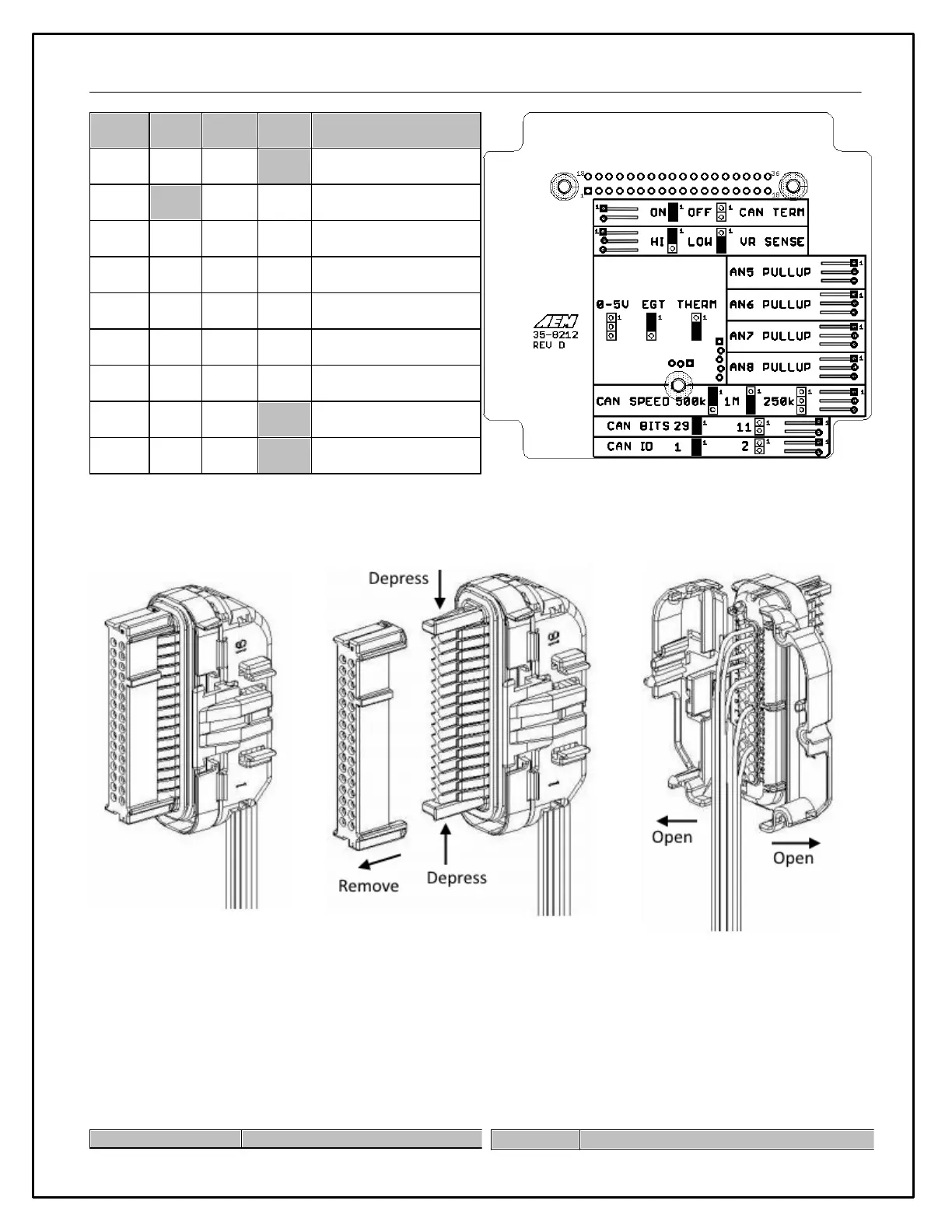
47
Sets 120 Ohm CAN
termination resistor
VR inputs 1 -2 trigger
sensitivity
Analog input 5 pull-up
resistor (Ohms)
Analog input 6 pull-up
resistor (Ohms)
Analog input 7 pull-up
resistor (Ohms)
Analog input 8 pull-up
resistor (Ohms)
First or second Sensor
module on bus
Jumper Position ( * = Default Position)
Inserting / Removing Pins
The clear retainer will have to be
removed to insert/remove pins
Depress the two black tabs
and slide retainer off
Unsnap and open the grey wings
to insert new pins
Note that 10 blue seals are included with the kit. For terminal locations that aren't being used, these must be
inserted to seal out water or other contaminants.
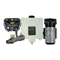
Connector and Accessory Part Numbers
The following is a list of compatible AEMnet accessories as well as part numbers for the main Module connector and
terminals.