63
AEMNet Network Wiring
AEMNet Network Wiring
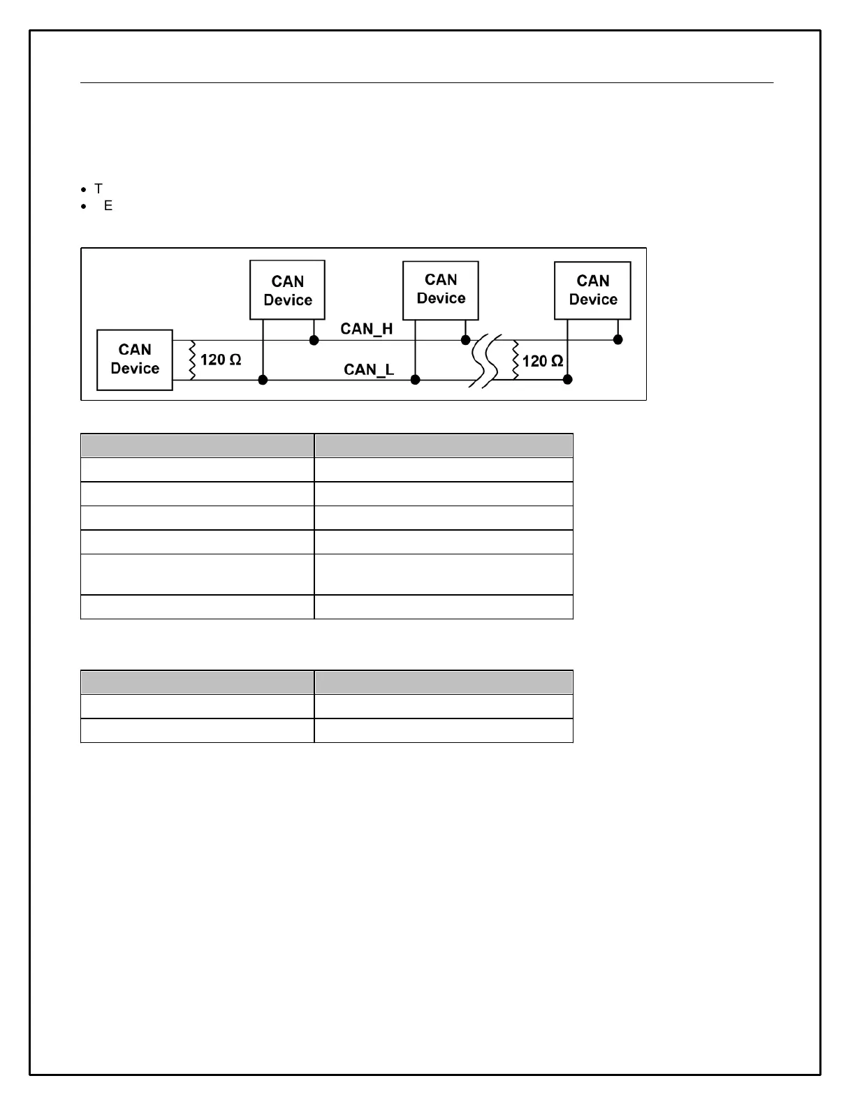
Refer to the following guidelines when wiring AEMnet (CAN) devices.
·
Twisted wire is required with >1 twist per inch.
·
AEMnet buses must be properly terminated. Termination resistors are 120 Ohms each, two total, located at the
physical ends of the bus wires.
Termination Resistors
30-2226, 6ch CAN Sensor Module
30-2212, 22ch CAN Sensor Module
30-560X & 30-570X CAN Dash
Software selectable, enabled by default
Hardware enabled by default on CAN A
(AEMNet)
Included, non-configurable
The following Deutsch DTM 4-pin termination plugs are available
AEMNet Termination Plug, Female
AEMNet Termination Plug, Male
Example Network Configurations
Example Network Configurations
Note: These diagrams assume that there are no other devices on the network