45
VR (Variable Reluctance) Inputs 1 -2
These inputs are suitable for connection to two-wire VR (variable reluctance) or "magnetic" style speed sensors.
Each input is composed of a pair of wires, positive (+) and negative (-), which must be connected to the sensor's
respective terminals. You may connect the Sensor Module to existing/OEM sensors or new sensors that have been
added to the vehicle. Common uses for these inputs would be for use with wheelspeed or driveshaft speed sensors.
Input Sensitivity / Jumper Selection
The "VR Sense" jumper configures the sensitivity, high or low, for these inputs. The default/recommended position
is "HI" which should work well for most situations. The "LOW" setting may be tried if there are low-speed signal
dropouts. Please refer to the section entitled Jumper Configuration for more information on how to change jumper
settings.
CAN Output
The measured frequency will be output in Hertz via CAN and will have to be scaled to speed (RPM, MPH, KPH, etc)
in the receiving device. The AEM CD series of dashes have this capability; please refer to the appropriate
documentation.
Tachometer Input
This input is suitable for measuring engine speed from a variety of sources such as an ignition coil's negative (-)
terminal or an ignition box/driver's 'tachometer' output. If your vehicle is equipped with an aftermarket high-output or
multi-strike ignition system, do *not* connect this input to the ignition coil. Instead, use the dedicated tachometer
output wire from your ignition system. "Flying Magnet" or VR style sensors should be connected to one of the VR
inputs and *not* the tachometer input.
CAN Output
The measured frequency will be output in Hertz via CAN and will have to be scaled to engine speed (RPM) in the
receiving device. The AEM CD series of dashes have this capability; please refer to the appropriate documentation.
Fuel Level Sensor Input
This input is suitable for connection to a resistive fuel level sensor. The output of these sensors typically varies from
slightly above 0 Ohms to a maximum of 240 Ohms. It is important that the AEM CAN Sensor Module is the only
device connected to the fuel level sensor. Tapping on to a sensor that is already connected to an OEM ECU (or
similar) will result in inaccurate readings.
CAN Output
The measured resistance will be output via CAN and will have to be scaled (typically linear) to fuel level (or
percentage) in the receiving device. The AEM CD series of dashes have this capability; please refer to the
appropriate documentation.
Note: The CAN output value, in Ohms, may appear to be slow to respond to input sensor signal changes. This is
as-intended since this input is heavily filtered to account for fuel level slosh.
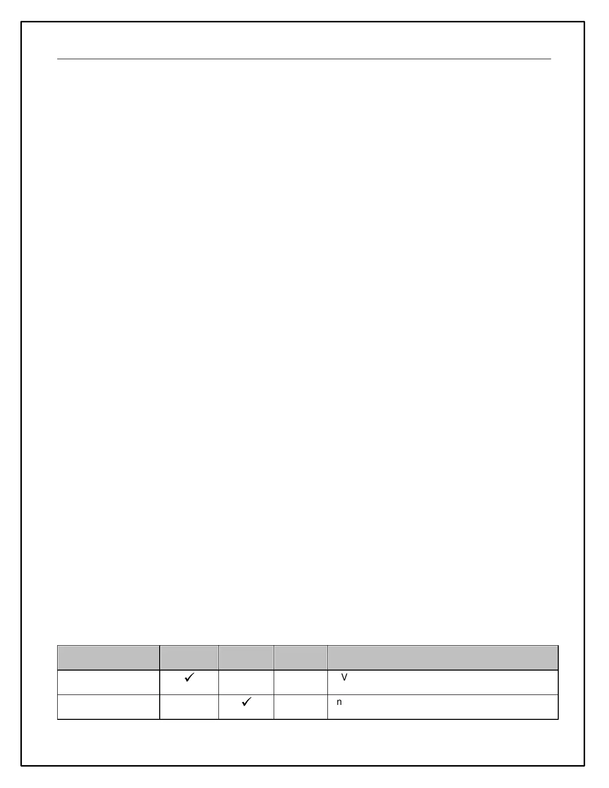
Digital Inputs 1 - 6
These inputs are suitable for measuring the frequency, duty cycle, and state of 0 - 12V signals. Each input
measures and outputs all three parameters without further configuration. Examples of common digital sensor
signals and typical applications are listed below.
Vehicle Speed Sensor
(VSS)
VSS frequency is proportional to vehicle speed.
Injector duty cycle is proportional to amount of fuel
used**