42
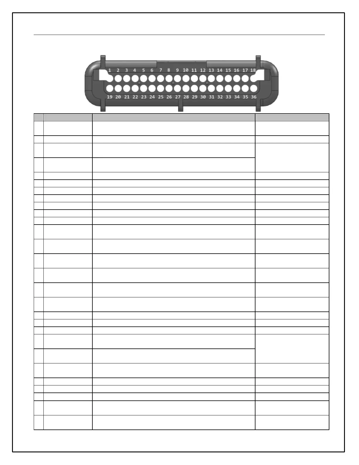
Device Pinout
Primary ignition/battery power input
VR / Magnetic Sensor input (Crank, wheel, or drive shaft
speeds)
VR / Magnetic Sensor input (Crank, wheel, or drive shaft
speeds)
0 - 250 Ohm fuel level sensor input
Engine speed input (negative coil terminal) 12V pull-up
Tach signal/Coil negative
5V sensor reference power output
5V sensor reference power output
Frequency, duty cycle %, and switch input / Active low, 12V
pull-up
Frequency, duty cycle %, and switch input / Active low, 12V
pull-up
Frequency, duty cycle %, and switch input / Active low, 12V
pull-up
Frequency, duty cycle %, and switch input / Active low, 12V
pull-up
Frequency, duty cycle %, and switch input / Active low, 12V
pull-up
Frequency, duty cycle %, and switch input / Active low, 12V
pull-up
Primary ignition/battery ground input
VR / Magnetic Sensor input (Crank, wheel, or drive shaft
speeds)
Non-Driven Wheel Speed VR
VR / Magnetic Sensor input (Crank, wheel, or drive shaft
speeds)
0-5V Analog input, 100k Ohm 5V pull-up
TPS / Throttle Position
Sensor
0-5V Analog input, 100k Ohm 5V pull-up
0-5V Analog input, 100k Ohm 5V pull-up
0-5V Analog input, 100k Ohm 5V pull-up
0-5V, Thermistor, RTD input, jumper selectable (470, 2200,
100k) 5V pull-up
Air/Fuel Ratio Analog Bank1
0-5V, Thermistor, RTD input, jumper selectable (470, 2200,
100k) 5V pull-up
Air/Fuel Ratio Analog Bank2