56
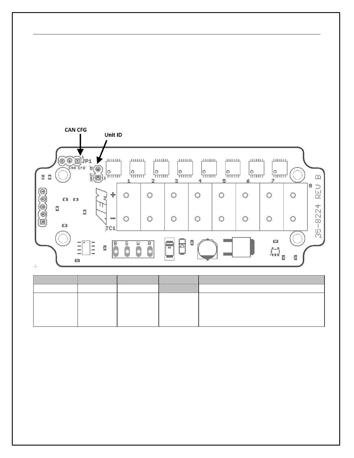
Jumper Configuration
Two configuration jumpers are located inside the enclosure of the Module. The cover may be removed by
unscrewing the four external screws to change the jumper positions if needed. The Module is delivered from the
factory in the most common configuration suitable for use with AEMnet (and other) devices; changing the jumper
positions is not typically necessary.
CAN CFG - The default position of 500 kb/s & 29 bit ID is correct for AEMnet. Please refer to the manufacturer's
documentation if you are using any third-party devices.
UNIT ID - The default position is correct if there is only a single AEM K-Type CAN Module installed on your network.
If you are using two Modules, the first unit must be set to 'UNIT 1' and the second to 'UNIT 2'.
First or Second Unit on Bus
Jumper Position ( * = Default Position)