INSPY. 1003. 4138305_03
11
over time.
Acoustic protection cover
(2)
Standard on all the NS versions, it consists
of a compartment in very thick steel sheet
and insulated entirely with soundproofi ng
material. It permits the acoustic power
emitted by the unit to be reduced and
furthermore protects the compressors from
the atmospheric agents.
4.3. HYDRAULIC COMPONENTS
Circulation pump No. 1/2 for optional
circuit configurator
Depending on the characteristics of the
pump chosen, it offers a useful head to
overcome the pressure drops in the system.
Whenever the reserve pump is present, this
is managed by the electronic board.
Expansion tank 2 per circuit (2x25 l)
(only in the versions with pump)
membrane type with nitrogen preloading.
4.4. SAFETY AND CONTROL COMPONENTS
Differential pressure switch IP54 1 per circuit
Located between the inlet and outlet of
the evaporator, it has the task of checking
that there is water circulation; otherwise,
the unit blocks.
Low pressure transducer
Allows displaying, on the microprocessor
card display, the value of the compressor's
suction pressure (one per circuit) on the
low-pressure side of the refrigerant circuit
High pressure transducer
Allows displaying, on the microprocessor
card display, the value of the compressor's
delivery pressure (one per circuit) On the
high pressure side of the refrigerant circuit
Double high pressure switch (manual + tool)
Factory-calibrated, it is placed on the high
pressure side of the cooling circuit, it shuts
down compressor operation in the case of
abnormal operating pressure.
Refrigeration circuit safety valves (HP, LP)
Calibrated at 22 bar HP - 16.5 LP, they cut
in relieving the overpressure in the case of
abnormal operating pressures.
− Fuses or thermomagnetic switches for
compressors protection to be specified
when ordered
− Fan protection thermomagnetic switch
− Secondary thermomagnetic switch
protection
4.5. ELECTRICAL COMPONENTS
Electrical panel
Contains the power section and the
management of the controls and safety
devices.
Door-block disconnecting switch
IT is possible to access the electrical panel
by disconnecting the voltage, then using
the opening lever of the panel itself. This
lever can be blocked with one or more
padlocks during maintenance, in order to
prevent the machine being powered up
accidentally.
Control keypad
Provides full control functions.
NB
For a detailed description refer to the user
manual.
Remote control panel (PVR3)
This allows the chiller command operations
to be given from a distance.
Pump version (example)
(2) IT IS POSSIBLE TO HAVE A FUR-
THER NOISE REDUCTION, WITH
DCPX AND AK ACCESSORIES.
For further information refer to
the chapter ACCESSORIES.
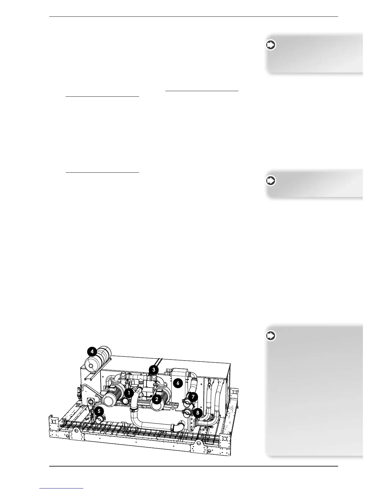
HYDRAULIC CIRCUIT KEY:
1. Evaporator input
2. Pump unit
3. Shut-off valves
4. Expansion tanks 2x25 litres
5. Water outlet with attachment
6. Total recovery
7. Inlet total recovery
8. Output total recovery
In any versions with or without
pumps, desuperheater and total
recovery, the water connections
are VICTAULIC with supplied joint
to weld
N.B.: the drawing is only an example
and reflects only the version with
pumps and total recovery.
All the electric cables are wired
for immediate recognition of
the electrical components