INSPY. 1003. 4138305_03
33
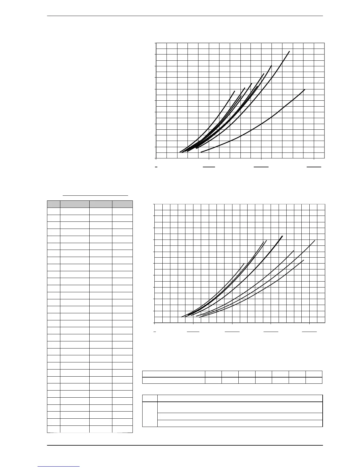
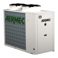
10. TOTAL PRESSURE DROPS
The pressure drops include:
− EVAPORATORS
− HYDRAULIC CIRCUITS
The diagram pressure drops are
related to an average water tempera-
ture of 10 °C. The following table shows
the correction to apply to the pressure
drops when the average water tem-
perature varies
Depending on the size, NS can have
from 1 to 3 evaporators with tube core.
NOTE:
The water outlet probe (SUW) with its
trap is free, near the electrical box,
remember to insert it in the collector
of the outlet hydraulic parallel, using a
sleeve of ½ inch.
Pressure drops (kPa)
Pressure drops (kPa)
NS
N° Compressor
(1) m
3
(2) m
3
1251 1 1,9 3,9
1401 1 2,2 4,4
1601 1 2,4 4,9
1801 1 2,9 5,9
2101 1 3,3 6,5
2401 1 3,7 7,5
1402 2 2,1 4,3
1602 2 2,4 4,8
1802 2 2,8 5,6
2002 2 3,2 6,3
2202 2 3,5 6,9
2352 2 3,6 7,3
2502 2 3,8 7,6
2652 2 4,0 8,1
2802 2 4,3 8,6
3002 2 4,6 9,3
3202 2 4,9 9,7
3402 2 5,4 10,7
3602 2 5,9 11,7
3902 2 6,2 12,4
4202 2 6,7 13,3
4502 2 7,0 14,0
4802 2 7,5 14,9
5002 2 7,8 15,6
5202 2 8,3 16,6
5402 2 8,8 17,6
5702 2 9,1 18,3
6003 3 9,6 19,2
6303 3 9,9 19,9
6603 3 10,4 20,8
6903 3 10,7 21,4
7203 3 11,2 22,4
10.1. MINIMUM WATER CONTENT
RECOMMENDED
(1) Minimum water content
(2)
Minimum water content in the case of process applications or operation with
low outside temperatures and low load.
Adjusting the outlet water temperature
project ∆t less than 5°C.
Water flow rate l/h
Water flow rate l/h
Average water temperature °C
5 101520304050
Multiplicational coefficient 1,02 1 0,985 0,97 0,95 0,93 0,91
0
20
40
60
80
100
120
140
160
180
200
0
50000 100000 150000
1251
2101
2401
1401 1402
1602
1601
1801
1802
0
20
40
60
80
100
120
140
160
180
200
0
50000 100000 150000 200000
2002
2202
2352
2502
2652 2802
3002
3
202
3402
Pressure drops NS ° (from1251 to 2401)
Pressure drops NS ° (from 2002 to 3402)