INSPY. 1003. 4138305_03
81
20. HYDRAULIC CIRCUIT
The NS consists of ONE - TWO - THREE CIR-
CUITS according to the size, together with:
STANDARD VERSION «00»
−
Evaporator 1 x Compressor (
the size from
1402 to 2802 have 1 evaporator and 2
compressors)
supplied with socket and Victaulic joints
− Differential pressure switch
− Water inlet probe SIW
− Water outlet probe SUW
NB
In the double and triple module, the water
outlet probe (WOP) with its trap, is free, next
to the electrical box, remember to insert it in
the collector of the outlet hydraulic parallel,
using a sleeve
of ½ inch.
VERSION with DESUPERHEATER «D»
− Evaporator 1 x circuit
supplied with socket and Victaulic joints
− Differential pressure switch
− Water inlet probe SIW
− Water outlet probe SUW
− Desuperheater with PLATE HEAT 1 x circuit
VERSION with PUMP «PA...PK»
− Evaporator 1 x circuit
supplied with socket and Victaulic joints
− Differential pressure switch
− Water inlet probe SIW
− Water outlet probe SUW
− Desuperheater with PLATE HEAT 1 x circuit
− Pump/s
− Expansion tanks 2 x 25 litres
20.1. EXTERNAL HYDRAULIC CIRCUIT REC-
OMMENDED
The selection and installation of components
outside the NS should be carried out by the
installer, who should work according to the
technical code of practice and in compli-
ance with the legislation in force in the coun-
try of destination (MD 329/2004).
Before connecting the pipes make sure that
they do not contain stones, sand, rust, slag
or any foreign bodies that may damage the
system. It is necessary to make a by-pass to
the unit to be able to carry out the cleaning
of the pipes without having to disconnect
the machine. The connection pipes must be
properly supported so as not to burden the
unit with their weight.
On the water circuit, it is advisable to install
the following instruments, if not foreseen in
the version you have:
1. Two pressure gauges of suitable size
(input and output section).
2. Two anti-vibration couplings (input and
output section).
3. Two shut-off valves (normal input section,
output section calibrating valve).
4. Two thermometers (input and output
section).
5. Expansion tanks
6. Pump
7. Accumulation tank
8. Flow switch
9. Safety valve
10. Charging unit
11. Discharge tap
It is necessary, that the water flow rate to the
chiller unit complies with the values reported
in the performance tables.
The systems loaded with anti-freeze or spe-
cific regulations, need the water backflow
system.
Special supply/recovery water, is carried out
with appropriate treatment systems.
20.2. SYSTEM LOAD
− Before starting the load, check that the
system drain tap is closed.
− Open all the drain valves of the system
and of the related terminals.
− Open the shut-off devices of the system.
− Start the filling by slowly opening the
water system load cock placed outside
the machine.
− When water begins to flow from the
terminal vent valves, close them and
continue loading up to read on the
gauge the value of 1.5 bar.
The system is loaded at a pressure between
1 and 2 bar.
It is advisable to repeat this operation once
the machine has worked for some hours and
to periodically check the system pressure,
restoring if it drops below 1 bar.
Check the hydraulic seal of the joints.
20.3. EMPTYING THE SYSTEM
When emptying the system:
1. If a prolonged stay is planed, winter
2. If a failure occurs or the need to oper-
ate in the system.
− Before you start emptying, place the
switch of the unit on “off”
and take off voltage.
− Discharge the differential
pressure switch
− Check that the water system
load/restore tap is closed
− Open the drain tap outside
the machine and all the vent
valves of the system and the
corresponding terminals.
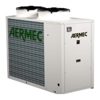
− Open the drain tap under
the tube core heat exchang-
er, see figure
− We recommend blow-
ing compressed air heat
exchanger to remove any
water stocks.
If the system uses glycol, this liquid
should not be drained to the en-
vironment because it is a pollutant. It must be
collected and, if possible, reused.
Drain tap
placed under the heat exchanger
WARNING:
If the unit will remain at standstill for
a long period during the winter, we
recommend the discharge of the sys-
tem (see below discharge operation)
or the addition of water with glycol.
Warning:
Glycol by law can not be drained
into the environment because it is
a pollutant