INSPY. 1003. 4138305_03
30
0.40
0.50
0.60
0.70
0.80
0.90
1.00
1.10
1.20
1.30
1.40
1.50
0.40
0.50
0.60
0.70
0.80
0.90
1.00
1.10
1.20
1.30
1.40
1.50
-5-6 -4 -3 -2 -1 0 1 2 3 4 5 6 7
8 9 10 1112 1314 15 16
-5-6 -4 -3 -2 -1 0 1 2 3 4 5 6 7
8 9 10 1112 1314 15 16
Cf
Ca
46°C
46°C 45°C
45°C
40°C
40°C
35°C
35°C
30°C
30°C
25°C
25°C
20°C
20°C
VERSION Y
VERSION Y
Outside air temperature
Outside air temperature
Evaporator water temperature (Δt=5°C)
0.40
0.50
0.60
0.70
0.80
0.90
1.00
1.10
1.20
1.30
1.40
1.50
0.40
0.50
0.60
0.70
0.80
0.90
1.00
1.10
1.20
1.30
1.40
1.50
-5-6 -4 -3 -2 -1 0 1 2 3 4 5 6 7
8 9 10 1112 1314 15 16
-5-6 -4 -3 -2 -1 0 1 2 3 4 5 6 7
8 9 10 1112 1314 15 16
Cf
Ca
46°C
45°C
45°C
46°C
40°C
40°C
35°C
35°C
30°C
30°C
25°C
25°C
20°C
20°C
VERSION Y
VERSION Y
Outside air temperature
Outside air temperature
Evaporator water temperature (Δt=5°C)
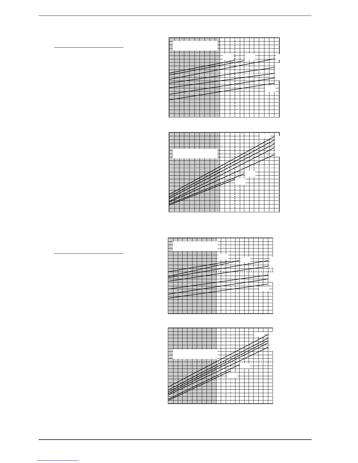
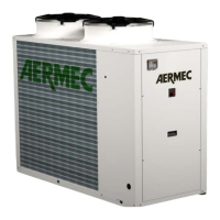
8.5. HIGH EFFICIENCY VERSION
EXCEPT FOR THE SIZES 5402
AND 5702
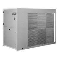
8.6. HIGH EFFICIENCY VERSION IN
SILENCED VERSION EXCEPT
FOR THE SIZES 5402 AND 5702
The cooling capacity yielded and the
input electrical capacity in conditions
other than rated conditions are ob-
tained by multiplying the rated values
(Pc, Pa) by the respective correction
coefficients (Cf, Ca).
The following diagrams allow you to
obtain the correction coefficients to be
used for the various versions of the de-
vices, in cold mode; next each curve
the external air temperature to which it
refers is shown.
KEY
Cf: correction coefficient of the
cooling capacity.
Ca: correction coefficient of the
input power.
FOR ∆t DIFFERENT FROM 5°C
Tab. 8.8.1. is used for the correction fac-
tors of the cooling capacity and input
power of the water consumption.
To take into account the exchanger
soiling, apply the relative fouling fac-
tors, Tab. 8.8.2.