49
TRS
24/07 5979398_00
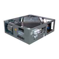
7.3 INSTALLATION LOCATION AND UNIT POSITIONING
— Make sure that the support surface is able to bear the weight of the machine and such as not to cause vibrations.
— Check that the support or support surface is perfectly horizontal to allow the correct coupling of the various sections.
— Do not position the unit in places where inammable gases, acid and aggressive and corrosive substances are present,
which can damage the various components irreparably.
— Leave a minimum amount of free space around the unit, as shown in the gure, so as to allow for installation, mainte-
nance and the replacement of components, such as coils, lters etc.
— If the unit is hung from the ceiling all the sections that make up the air handling unit must be connected to the ceiling.
THE NON-COMPLIANCE OF THE GAP SPACES MAY LEAD TO THE INACCESSIBILITY TO UNIT COMPONENTS,
MAKING THEM IMPOSSIBLE FOR ANY MAINTENANCE.
EA= exhaust air
OA= fresh air
RA= return air
SA= supply air
Model A Inner celing height B
mm mm
TRS252 599 320
TRS352 804 320
TRS502 904 320
TRS652 884 450
TRS802 1134 450
TRS1002 1216 450
TRS1302 1216 450