60
TRS
24/07 5979398_00
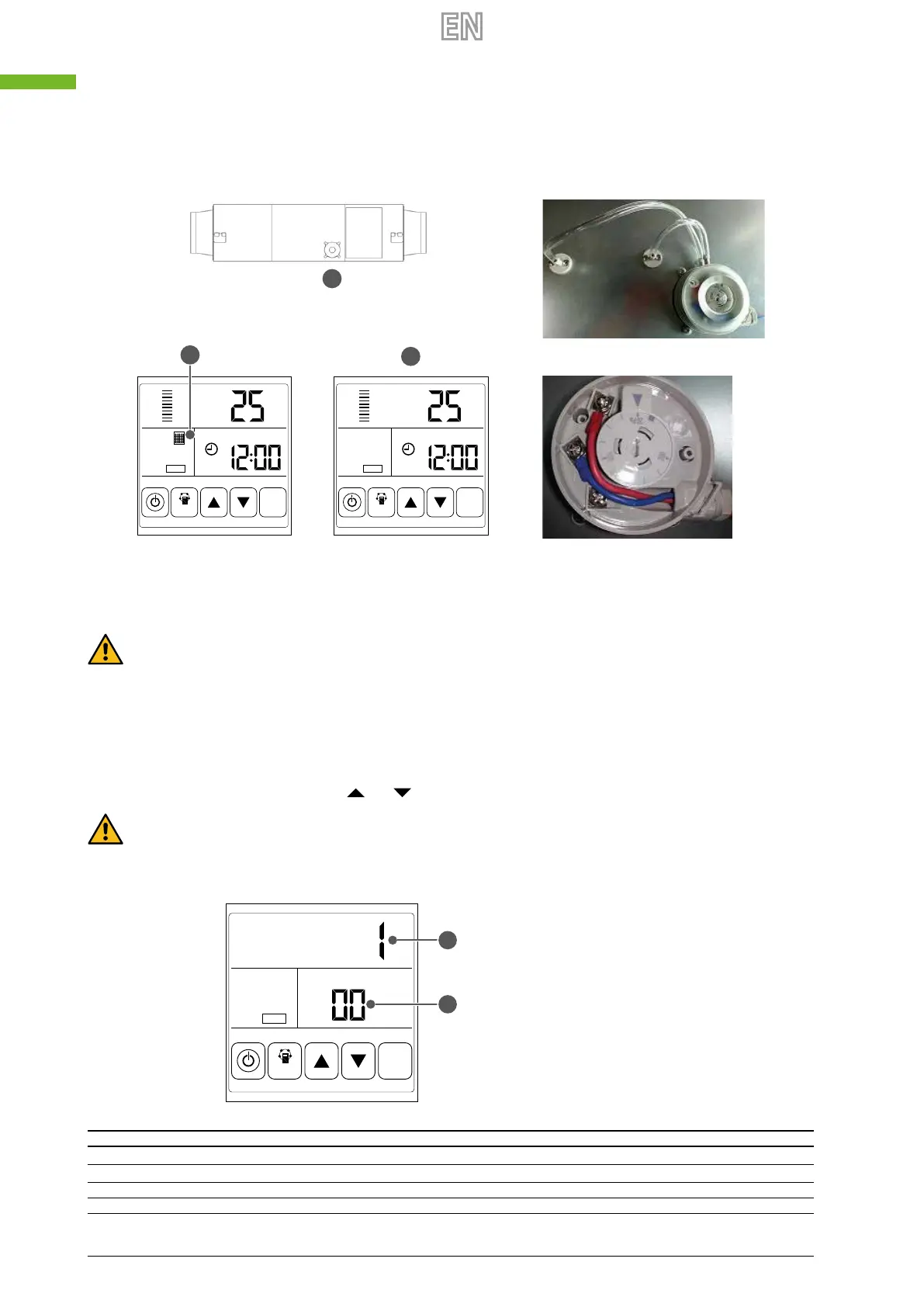
6. Filter alarm: the lter pressure switch on the access door is used to monitor lter ePM
2,5
. When the pressure dierence
is greater than set value, the switch transmits a “dirty lter” signal to the control system. The lter alarm signal will ash
on the LCD display to remind the use to clean or replace the lter.
A Pressure switch
B Filter Alarm ON
C Filter Alarm OFF
RA
TH
°C
COMM
MODE
SET
RA
TH
°C
COMM
MODE
SET
A
B
C
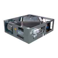
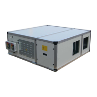
Attention: the correct pressure switch factory setting is 150 pa. If need, as showed by the picture, open the plastic
cover and use a screwdriver to set the correct pressure dierence. Pressure switch is installed by manufacturer ex-fac-
tory, it is wired to the PCB PORT 4. For the details please refer to the wiring diagram on dedicated chapter "9Wiring
diagramp.53".
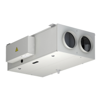
7. Setting the parameters: to access the parameter setting interface, keep the MODE key pressed for 6 seconds until you
hear a beep. To pass from one parameter to another (from 00 to 25), press the SET key briey. When the display shows
the number of the parameter you want to modify, press the MODE key briey. The parameter value will ash in the upper
right corner. To modify it, press the keys
and ; the press SET to save the settings.
Warning: once the parameters have been set, the system takes about 15 seconds to register them. The power supply
must not be disabled during this time. To set the appropriate parameters for the various requests, refer to the param-
eter table below.
A Parameter Value
B Parameter Number
COMM
MODE
SET
A
B
Number Description Range Default Unit Position
00 Power to auto restart 0-1 1 Circuit board
01 Electrical heater (n.d.) 0-1 0 Control panel
02 By pass opening temperature X 5-30 19 °C Circuit board
03 By pass opening temperature Y 2-15 3 °C Circuit board