Assembly instructions EN CS 8 - CS 12 Date 01.06.2021 Version 4.5 29–56
5 Design and description
This chapter provides an overview of the compact slide structure and
functioning.
Design compact slide
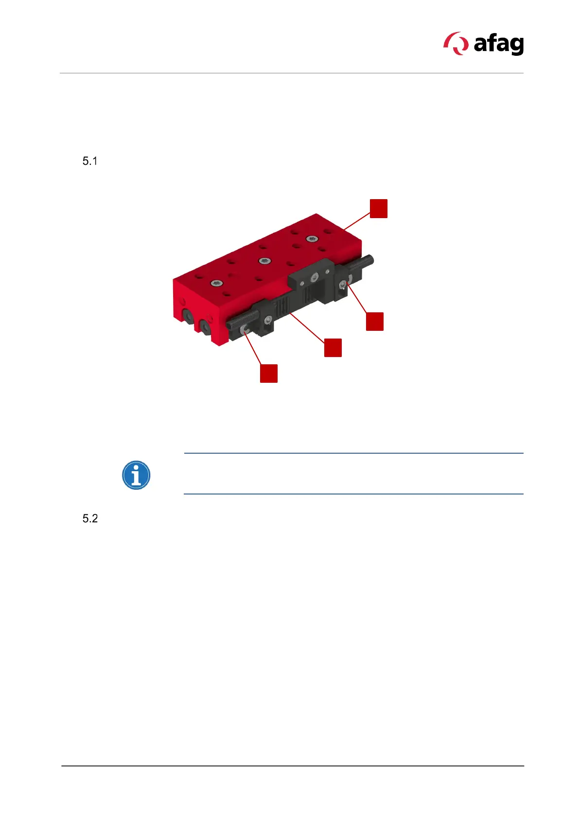
Fig. 8 Design of the CS module
1. Base body 3. Stop screw with integrated shock absorber
2. Slide 4. Fastening screw for shock absorber
The shock absorbers used are precision-engineered parts. Do not overtighten
the fixing screw (Fig. 8, 4), otherwise the shock absorber may be damaged!
Product description
Compact slides of the CS 8 and CS 12 series are precision devices. In order
ensure safe and reliable operation it is important that the modules are handled
with care.
The compact slides are highly compact, pneumatic modules and are used for
the shock-free linear movement of permanently mounted loads in the defined
ambient and operating conditions.
The assembly position of the compact slide can be vertical or horizontal.
The CS 8 - CS 12 modules consists of the base body (Fig. 8, 1) with the
pneumatic connections and the cylinder that moves the slide (Fig. 8, 2). The end
positions are each adjusted via a stop screw with integrated shock absorber.
The end position can optionally be sensed by means of a∅ 3 mm inductive
switch (not included in the scope of delivery,
Chap. 5.3 „Accessories“). The
proximity switch is fixed in the C-slot of the base body.