Installation, assembly & setting
Assembly instructions EN CS 8 - CS 12 Date 01.06.2021 Version 4.5 39–56
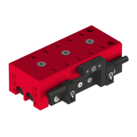
6.5.2 Adjustment of the elastomer shock absorber
The elastomer shock absorber may be operated with a max. load of 0.2 kg
on the CS 8.
Do not use the CS 12 module with elastomer shock absorber in unthrottled
operation!
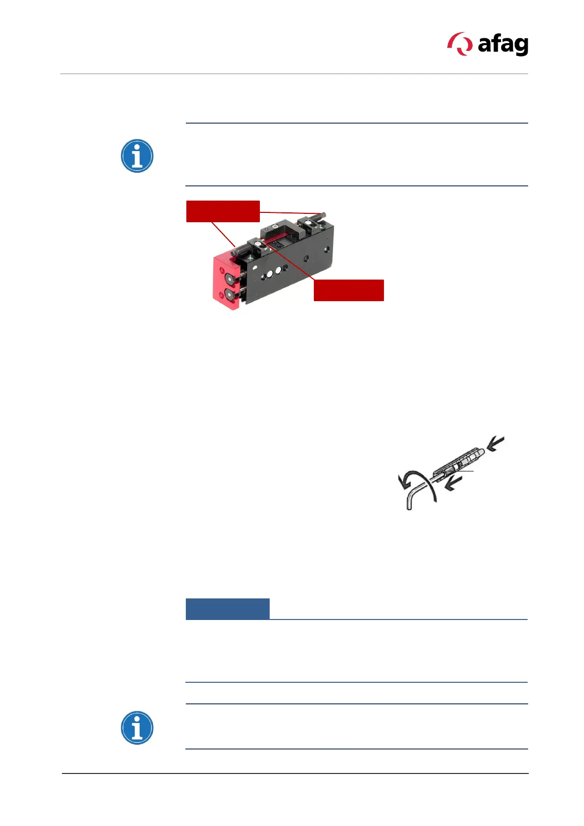
Fig. 13 Adjustment of the shock absorber
The energy values in the technical data apply with the adjustment pin fully
screwed in, i.e. with the maximum stroke set (stroke max.). With appropriate
stroke reduction, the defined fixed end position can still be reached with less
energy or with a low drive force (F
A
).
By default, this applies to the rear position on the CS 8, since the return stroke
force is less than 30 N.
Procedure:
1. Unscrew the adjustment pin until the
defined end position is reached with the
drive force (F
A
) present.
2. Checking the damper in the test run. The
slide must not hit hard in the process.
Technical data of elastomer shock absorbers:
Type Max. Stroke H Max. Energy Driving force Fa
ASED M5x0.5-1 (CS 8) 2.8 mm 0.02 J 30 N
ASED M5x0.5-1 (CS 12) 3.1 mm 0.03 J 40 N
If the desired stroke cannot be set with the shock absorber, the insert strip
must be loosened and mounted rotated by 180°.
Exceeding the specified load capacities will destroy the CS module.
For a clean approach to the end positions, an exhaust air throttle is required
to adjust the stroke movement. If the specified operation times
observed, the slide may be destroyed.
pin