Positioning the DR 17e
When performing an exposure, keep in mind the following detector
orientation aids:
• tube side
• patient orientation marker
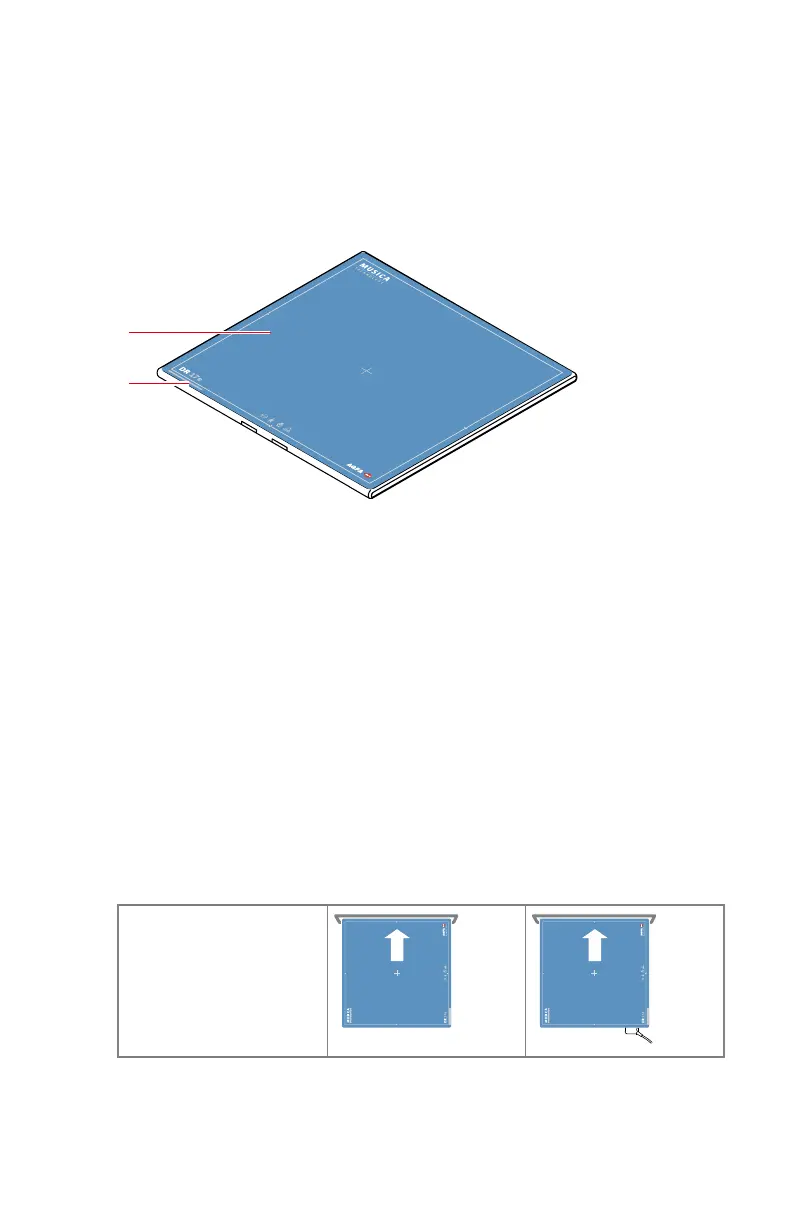
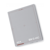
Figure 26: Detector orientation aids
1. Tube side of the detector
2. Location of the patient orientation marker
The detector must be positioned with the patient orientation marker at the
lower side of the region of interest.
The detector orientation and the patient orientation are exposure settings on
the NX workstation. The detector orientation is displayed on the NX
workstation as cassette orientation.
The user is responsible for the correct and clear marking on the left or right
side of the image to eliminate possible errors.
Below some examples to illustrate the importance of the detector orientation
marker.
Table 6: Table with bucky
Table with bucky
88 | DR 10e, DR 14e, DR 17e | Getting started
0370C EN 20200228 1449