EasyManua.ls Logo

Agilent Technologies 33250A User Manual

Agilent Technologies 33250A
336 pages
To Next Page IconTo Next Page
To Previous Page IconTo Previous Page
Page #103 background imageLoading...
Page #103 background image
103
Chapter 3 Features and Functions
Arbitrary Waveforms
3
Arbitrary Waveforms
There are five built-in arbitrary waveforms stored in non-volatile memory
.
You can also store up to four user-defined waveforms in non-volatile
memory in addition to one in volatile memory. Each waveform can
contain between 1 (a dc voltage) and 65,536 (64K) data points.
Refer to chapter 7, “Tutorial”, for more information on the internal
operation of downloading and outputting an arbitrary waveform.
To Create and Store an Arbitrary Waveform
This section gives an example which shows you how to create and store
an arbitrary waveform from the front panel. To download an arbitrary
waveform from the remote interface, see “Arbitrary Waveform Commands”
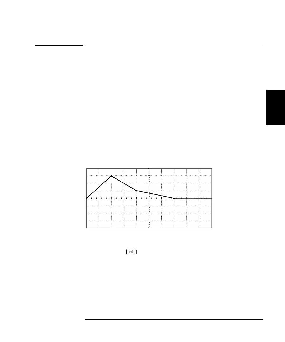
starting on page 198. For this example, you will create and store the
ramp waveform shown below using four waveform points.
1 Select the arbitrary waveform function.
When you press to select the arbitrary function, a temporary
message is displayed indicating which waveform is currently selected.
2 Start the arbitrary waveform editor.
Press the Create New softkey to start the waveform editor. While in the
waveform editor, you define the waveform by specifying time and voltage
values for each point in the waveform. When creating a new waveform,
the previous waveform in volatile memory is overwritten.
Volt/Div = 1 Volt
Time/Div = 1 ms
2
3
4
1
1

Table of Contents

Other manuals for Agilent Technologies 33250A

Question and Answer IconNeed help?

Do you have a question about the Agilent Technologies 33250A and is the answer not in the manual?

Agilent Technologies 33250A Specifications

General IconGeneral
Frequency Range1 µHz to 80 MHz
Amplitude Range10 mVpp to 10 Vpp into 50 Ω
Output Impedance50 Ω
Modulation TypesAM, FM, PM, FSK, PWM
Sweep ModesLinear, Logarithmic
Function Generator TypeArbitrary
WaveformsSine, Square, Ramp, Triangle, Noise, Arbitrary
InterfaceGPIB, USB

Summary

The Front Panel at a Glance

Front Panel Controls Overview

Identification and description of front panel keys and controls.

Front-Panel Number Entry

The Rear Panel at a Glance

Rear Panel Connectors and Terminals

Identification and function of rear panel connectors and terminals.

Quick Start

To Prepare the Function Generator for Use

Initial setup steps and item verification.

To Set the Output Frequency

Procedure for configuring the output frequency.

To Set the Output Amplitude

Procedure for configuring the output amplitude.

To Set a DC Offset Voltage

Procedure for setting the DC offset voltage.

Front-Panel Menu Operation

To Configure the Remote Interface

Steps to set up GPIB or RS-232 communication.

Features and Functions

Output Configuration

Information on configuring output parameters like function, frequency, and amplitude.

Arbitrary Waveforms

Information on creating, storing, and outputting arbitrary waveforms.

Remote Interface Configuration

Configuration of GPIB and RS-232 interfaces.

Remote Interface Reference

SCPI Command Summary

Comprehensive list and syntax of SCPI commands.

Output Configuration Commands

SCPI commands for controlling output parameters.

Arbitrary Waveform Commands

SCPI commands for downloading and managing arbitrary waveforms.

Error Messages

Command Errors

List and explanation of errors related to invalid commands.

Execution Errors

List and explanation of errors during command execution.

Specifications

FREQUENCY CHARACTERISTICS

Frequency ranges and accuracy for different waveform types.

OUTPUT CHARACTERISTICS

Specifications for amplitude, flatness, units, and impedance.

Related product manuals