EasyManua.ls Logo

Agilent Technologies 33250A User Manual

Agilent Technologies 33250A
336 pages
To Next Page IconTo Next Page
To Previous Page IconTo Previous Page
Page #166 background imageLoading...
Page #166 background image
166
Chapter 4 Remote Interface Reference
Pulse Configuration Commands
4
Pulse Configuration Commands
See also “Pulse Waveforms” starting on page 64 in chapter 3.
This section describes the low-level commands used to program the
function generator to output a pulse waveform. To select the pulse
function, use the FUNC PULS command (see page 153). Refer to the
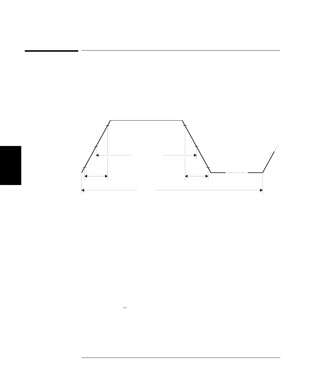
diagram below for the command descriptions that follow.
PULSe:PERiod {<seconds>|MINimum|MAXimum}
PULSe:PERiod? [MINimum|MAXimum]
Set the period for pulses. Select a period from 20 ns to 2000 seconds.
The default is 1 ms. MIN = 20 ns. MAX = 2000 seconds. The :PER? query
returns the period of the pulse waveform in seconds.
The specified period must be greater than the sum of the pulse width
and the edge time as shown below. The function generator will adjust
the pulse width and edge time as needed to accommodate the specified
period. From the remote interface, a “Data out of range” error will be
generated and the period will be adjusted as described.
Period >
Pulse Width + (1.6 X Edge Time)
Rise Time
Fall Time
10%
90%
50%
10%
90%
50%
Pulse Width
Period

Table of Contents

Other manuals for Agilent Technologies 33250A

Question and Answer IconNeed help?

Do you have a question about the Agilent Technologies 33250A and is the answer not in the manual?

Agilent Technologies 33250A Specifications

General IconGeneral
Frequency Range1 µHz to 80 MHz
Amplitude Range10 mVpp to 10 Vpp into 50 Ω
Output Impedance50 Ω
Modulation TypesAM, FM, PM, FSK, PWM
Sweep ModesLinear, Logarithmic
Function Generator TypeArbitrary
WaveformsSine, Square, Ramp, Triangle, Noise, Arbitrary
InterfaceGPIB, USB

Summary

The Front Panel at a Glance

Front Panel Controls Overview

Identification and description of front panel keys and controls.

Front-Panel Number Entry

The Rear Panel at a Glance

Rear Panel Connectors and Terminals

Identification and function of rear panel connectors and terminals.

Quick Start

To Prepare the Function Generator for Use

Initial setup steps and item verification.

To Set the Output Frequency

Procedure for configuring the output frequency.

To Set the Output Amplitude

Procedure for configuring the output amplitude.

To Set a DC Offset Voltage

Procedure for setting the DC offset voltage.

Front-Panel Menu Operation

To Configure the Remote Interface

Steps to set up GPIB or RS-232 communication.

Features and Functions

Output Configuration

Information on configuring output parameters like function, frequency, and amplitude.

Arbitrary Waveforms

Information on creating, storing, and outputting arbitrary waveforms.

Remote Interface Configuration

Configuration of GPIB and RS-232 interfaces.

Remote Interface Reference

SCPI Command Summary

Comprehensive list and syntax of SCPI commands.

Output Configuration Commands

SCPI commands for controlling output parameters.

Arbitrary Waveform Commands

SCPI commands for downloading and managing arbitrary waveforms.

Error Messages

Command Errors

List and explanation of errors related to invalid commands.

Execution Errors

List and explanation of errors during command execution.

Specifications

FREQUENCY CHARACTERISTICS

Frequency ranges and accuracy for different waveform types.

OUTPUT CHARACTERISTICS

Specifications for amplitude, flatness, units, and impedance.

Related product manuals