316
Chapter 7 Tutorial
Burst
7
As an example, suppose that your application requires two 5 MHz sine
waveforms that are exactly 90° out of phase from one another. You can
use two 33250A’s as described below. First, designate one function
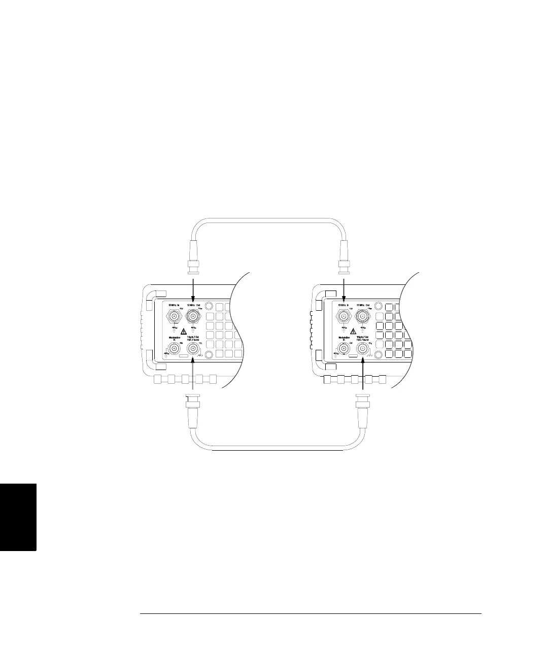
generator as the “master” and the other as the “slave”. As shown below,
connect the master’s 10 MHz Out connector to the slave’s 10 MHz In
connector using a high-quality coaxial cable. This configuration will
ensure that both instruments will generate exactly the same frequency
and that there will not be any long-term phase shift between the two
instruments. Next, connect the two Trig In/Out connectors together to
allow the master to trigger the slave.
After making the connections shown above, follow the steps below to
configure the two instruments.
1 Configure both instruments to output a 5 MHz sine waveform.
2 On both instruments, enable the N-Cycle burst mode, set the burst count
to three cycles, and set the starting phase to 0 degrees.
3 On the “master”, select the Internal trigger source and enable the
“trigger out” signal with a rising edge from the Trig Out connector.
Master
Slave