To connect the microphone adapter
The Microphone Adapter and Power Supply (option UK4) simplifies microphone
connections. The mic connector on the analyzer’s front panel provides 8 Vdc to power
the adapter. The adapter’s internal power supply uses a step-up converter to provide
28 V and 200 V on the seven-pin input connectors. The 28 V pins power the
microphone pre-amplifiers. The 200 V pins polarize the condenser microphone
cartridges.
1 Flip the bail handle down to support the front of the analyzer.
2 Insert the threaded ends of the adapter’s two knurled knobs into the standoffs on the
bottom of the analyzer’s case, then tighten the knobs with your fingers.
3 Attach the adapter’s mic cable to mic connector on the analyzer’s front panel.
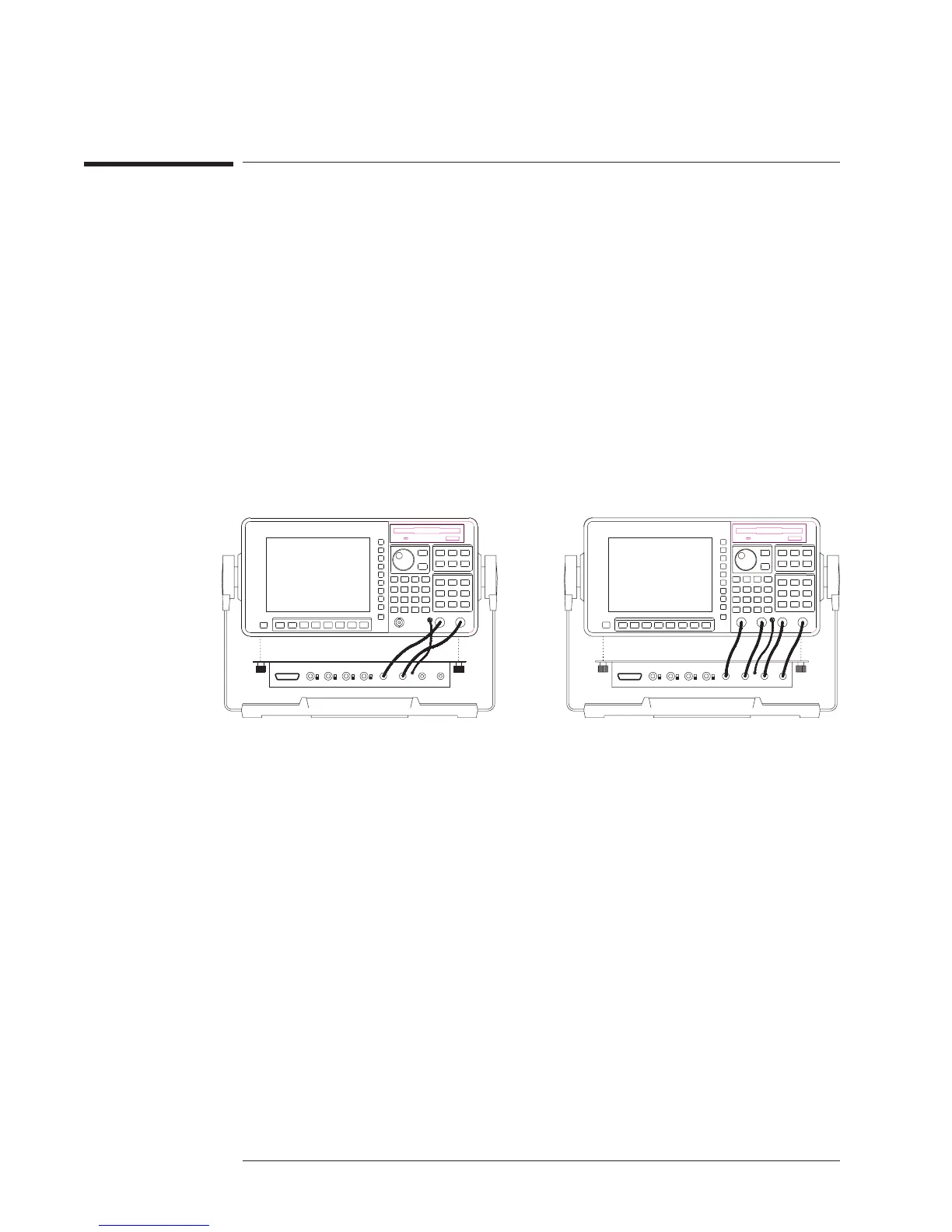
4 Connect the adapter’s BNCs to the corresponding BNCs on the analyzer’s front panel.
Standard 2 channel Agilent 35670A Optional 4 channel Agilent 35670A
Preparing the Analyzer for Use Agilent 35670A
To connect the microphone adapter
2-16

 Loading...


