148 Chapter2
Making Adjustments
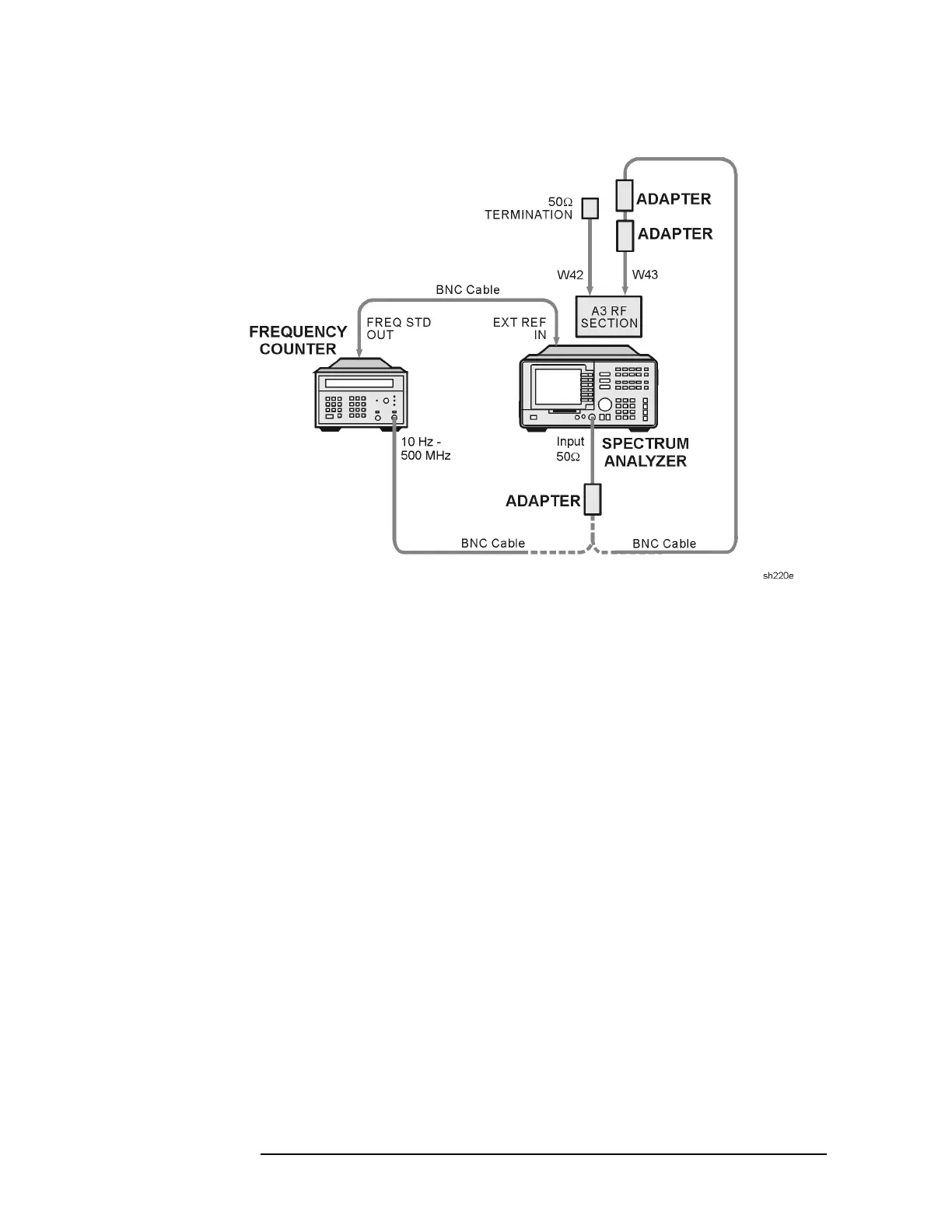
24. Tracking Oscillator for Option 010
Figure 2-37 Tracking Oscillator Adjustment Setup
15.Set the analyzer
LINE switch to on. Press AUX CTRL, TRACK GEN,
SRC PWR ON OFF (ON). Allow the analyzer to warm up for at least 5
minutes. Set the controls as follows:
CENTER FREQ ............................................ 300MHz
SPAN .....................................................................0Hz
16.Set the microwave frequency counter controls as follows:
SAMPLE RATE .........................................FullyCCW
10 Hz-500 MHz SWITCH ................. 10Hz-500MHz
500 MHz-26.5 GHz SWITCH ............ 10Hz-500MHz
50 Ω - 1 MΩ SWITCH ..........................................50Ω
17.Remove the screw, located on the front of the tracking generator,
used to seal the tracking oscillator adjustment.
18.On the analyzer, press
AUX CTRL, TRACK GEN, MAN TRK ADJUST, 0,
Hz.
19.Record the microwave frequency counter reading in Table 2-9 as F1.
20.On the analyzer, press
MAN TRK ADJUST, 4095, Hz.
21.Record the microwave frequency counter reading in Table 2-9 as F2.

 Loading...


