408 Chapter10
Analyzer Options and Block Diagrams
Troubleshooting Analyzer Options
Troubleshooting Analyzer Options
This section provides information to aid in troubleshooting options
installed in the 8590 Series analyzers.
Tracking Generator 8590L, 8591C, and
8591E Option 010, 011
Refer to Figure 10-1, Tracking Generator Block Diagram, for an
overview of operation for the tracking generator and its connection to
the standard analyzer.
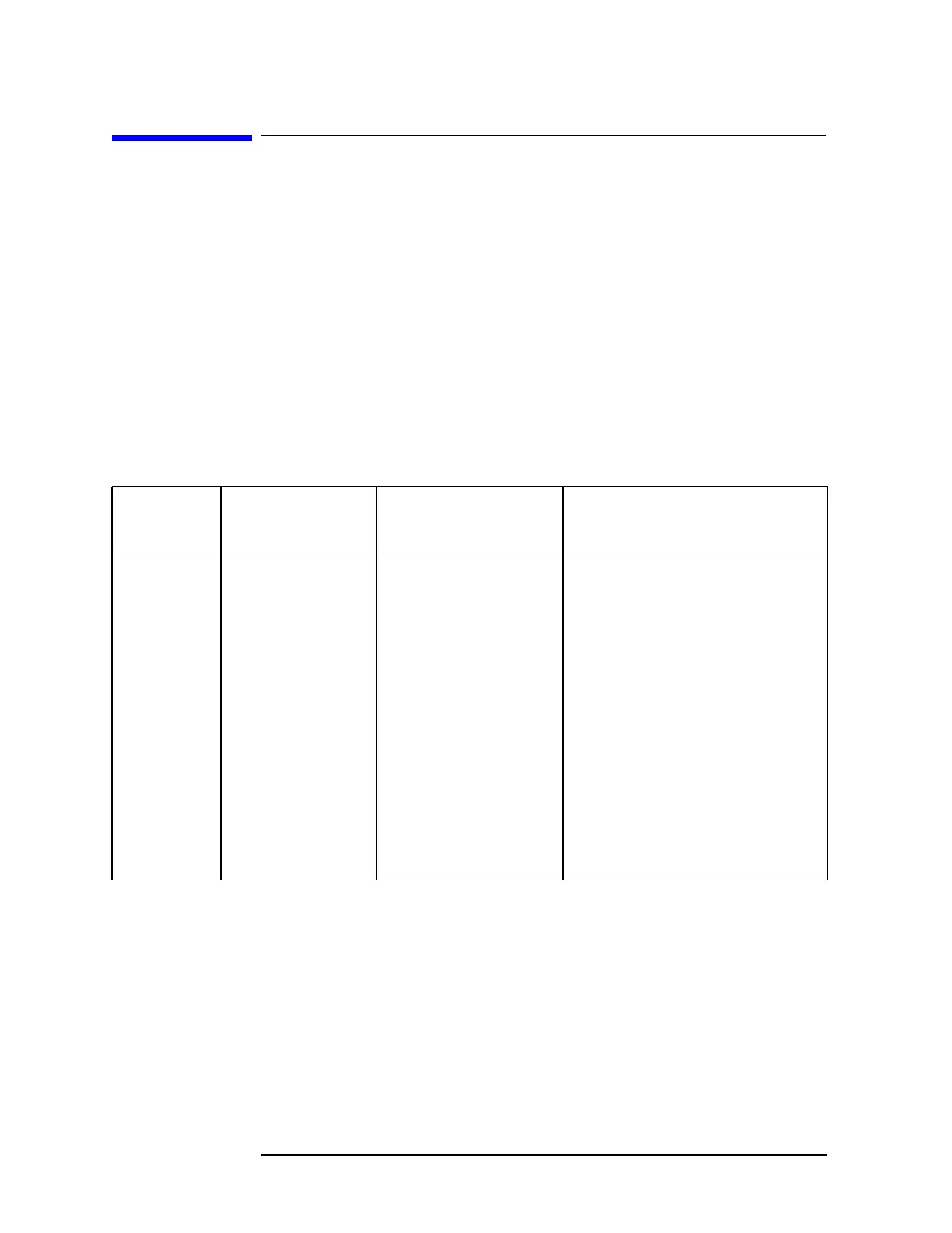
The signals present on the W33 wire harness at A7A1J7 are detailed in
Table 10-2 and on Figure 10-1.
Table 10-2 Tracking Generator Control Signals at A7A1J7
A7A1J7
Connector
Pin
W33
Wire Color
Mnemonic Signal Description
1 Brown MOD_DRIVE Modulator drive voltage
2 No Connection
3 Orange D1 Drain voltage (−.5 to −2.0V)
4 Yellow G1 Gate 1 bias voltage (5.4 V)
(−0.5 to −2.0 V)
5 Green D2 Drain voltage (−.5 to −2.0V)
6 Blue G2 Gate 2 bias voltage (5.4 V)
(−0.5 to −2.0 V)
7 Violet ATN_30 Control for 30 dB attenuator step
8 Gray +15_X3 Switched +15 VF
9 White ATN_20 Control for 20 dB attenuator step
10 Black +15VF +15 VF for Amplifier/Detector
11 White/Brown ATN_10 Control for 10 dB attenuator step
12 White/Red +15 VF +15 VF for Attenuator

 Loading...


