4-8 Option 100 Fault Location and SRL
Making SRL Measurements
How to Make and Interpret SRL Measurements
3. Connect the Equipment
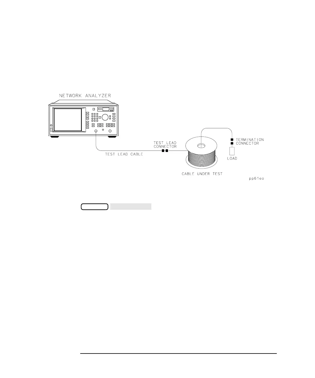
The basic equipment setup for SRL measurements is illustrated in
Figure 4-4.
Figure 4-4 Basic SRL Measurement Setup
You may want to verify that the sweep time is valid for the length of
cable being measured. To verify the sweep time is correct, press
. Then use the front panel knob, the front
panel arrow keys, or the numeric keypad to vary the sweep time. Choose
the fastest sweep time that does not cause a change in the response.
4. Determine the Connector Model
After connecting the cable under test as shown in Figure 4-4, you should
determine the connector model for the best response. The connector
model may need to be determined each time a new cable is tested.
When using connectors that have very consistent interfaces, modeling
the connector for each new connection to a cable may not be required.
When using connectors that do not have a repeatable interface contact,
modeling the connector for each new connection to a cable is necessary.
For some SRL measurements, the response of the connector can be
critical for obtaining a true measurement of structural return loss. For
example, a connector with a return loss of 30 dB will swamp out SRL
responses less than about −20 dB. A connector with a 40 dB return loss
will provide a more accurate measurement of the −20 dB responses.
SWEEP
 Loading...


