3-16 Option 100 Fault Location and SRL
Making Fault Location Measurements
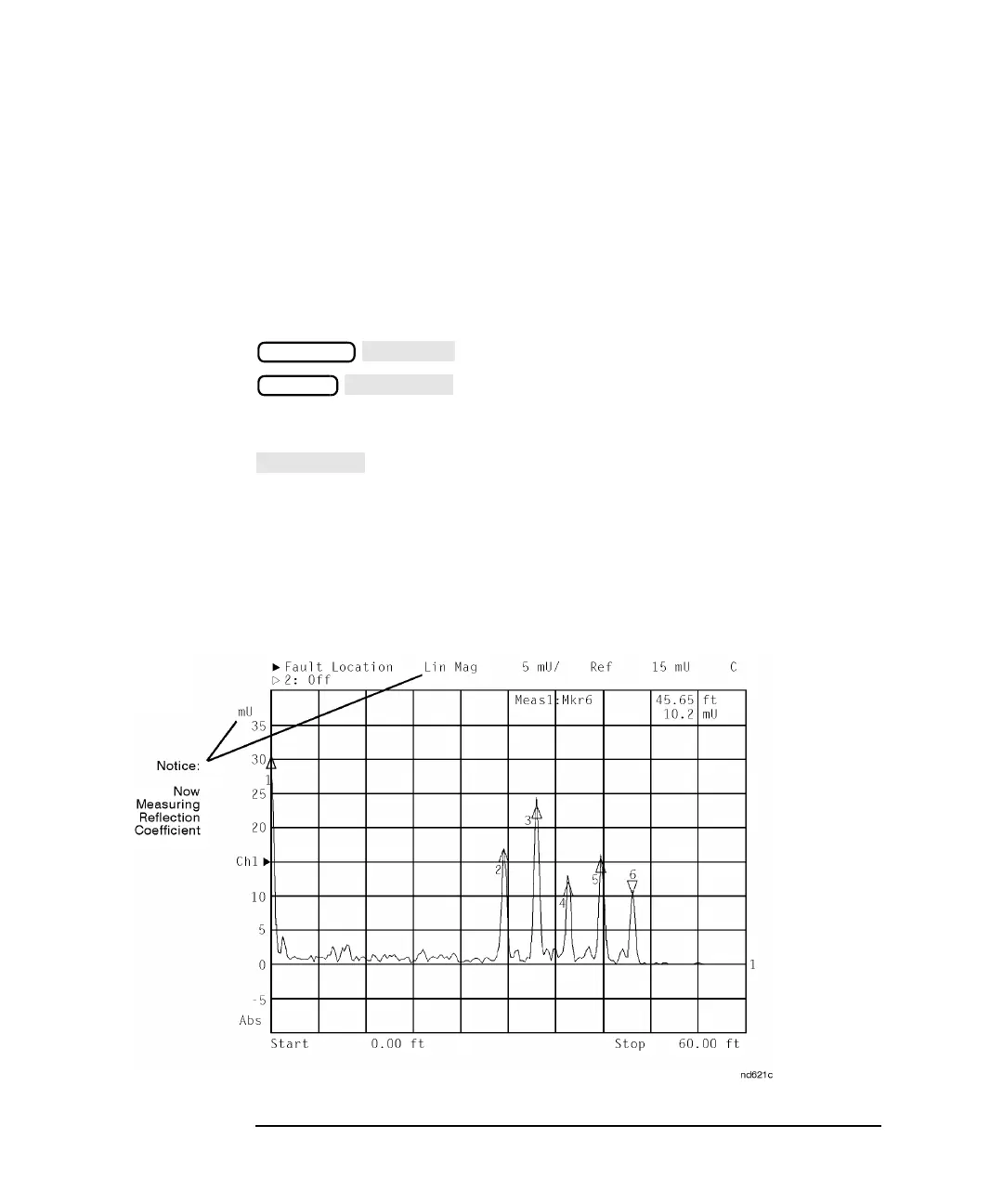
Example Fault Location Measurements
Example 2: Identify Mismatches as the
Magnitude of Reflection Coefficient
For this example, use the same equipment setup and steps to place
markers on responses as instructed in example 1.
Press the following keys:
This example is very similar to example 1 except that the responses are
measured in terms of reflection coefficient rather than return loss.
is used to optimize the viewing of the data trace within the
display area.
As in example 1, the response designated by marker 1 identifies the
cable connector. Markers 2, 3, 4, and 5 identify barrel connectors
separated by 4 feet. Marker 6 identifies the 50 ohm termination.
Figure 3-8 Example 2: Identify Mismatches as the Magnitude of Reflection
Coefficient
FORMAT
SCALE