Option 100 Fault Location and SRL 3-15
Making Fault Location Measurements
Example Fault Location Measurements
5.
Press to activate marker 2 and use the front panel knob, the up
and down arrow keys, the , or the
functions to place marker 2 on the next response
as shown in Figure 3-7.
6. Repeat the previous step for markers 3 through 6.
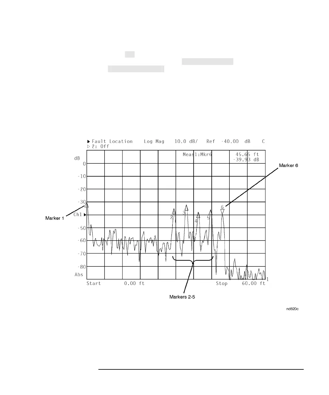
In this example, the first marker displays the return loss at the cable
connector. Markers 2, 3, 4, and 5 identify barrel connectors separated by
4 feet. Marker 6 identifies the 50 ohm termination.
Figure 3-7 Example 1: Identify Mismatches Expressed as Return Loss