7-10 Option 100 Fault Location and SRL
Characterizing and Verifying Antenna Systems
Installation and Maintenance Planning
Installation and Maintenance Planning
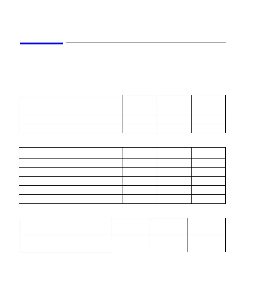
Installation and maintenance planning is used to verify the performance
of the antenna system. The following tables can be used to enter test
results along with the specified limits and pass/fail margins. This allows
for quick monitoring and recording of the antenna system's performance.
Table 7-1 Incoming Inspection
Table 7-2 Installation
Table 7-3 Maintenance
Characteristic Limit/Spec Test Result Date/Time
Cable attenuation at 900 MHz (dB/100 ft.)
Characteristic impedance
Velocity factor
Characteristic Limit/Spec Test Result Date/Time
Insertion loss
Cable attenuation (dB/100 ft.)
System return loss (dB)
Cable length (ft.)
Connector loss (fault loc., dB)
Characteristic
Pass/Fail
Margin
Test Result Date/Time
System return loss (dB)
Connector loss (fault loc., dB)