Maintaining the Instrument
Leak Testing: General Information
103
Leak Testing: General Information
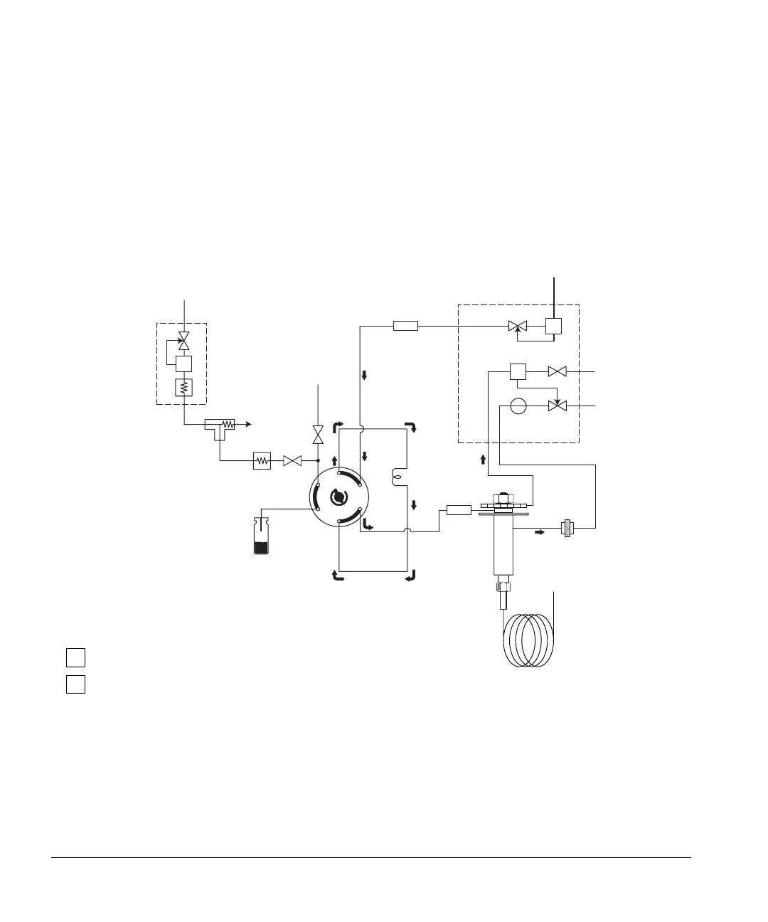
Refer to Figure 26 and Figure 27, which show the flow paths for all gases used
in each type of headspace installation.
Figure 26. Flow paths for a G1289 to 6890 GC installation
1
2
3
4
5
6
Flow paths before GC prep-run
Carrier gas in
Vial pressure
EPC Flow Module
Septum purge
Split vent flow
Purge
Split vent trap
Column
Column flow
ZDV union
ZDV
Sample
S1
S2
Flow
Needle
Headspace vial
PS
PS
FS
PCV1
PCV2
Headspace Sampler
GC
gas in
restrictor
Aux. bleed
fitting
loop
valve
union
4ml/min
(Total flow
200 ml/min)
Aux EPC
Module
3ml/min
FS
PS
Flow sensor
Pressure sensor
Legend
S1
S2
Pressurize valve
Vent valve

 Loading...