Agilent InfinityLab LC Series 1260 Infinity II FLD User Manual 25
Introduction to the Fluorescence Detector
1
Optical Unit
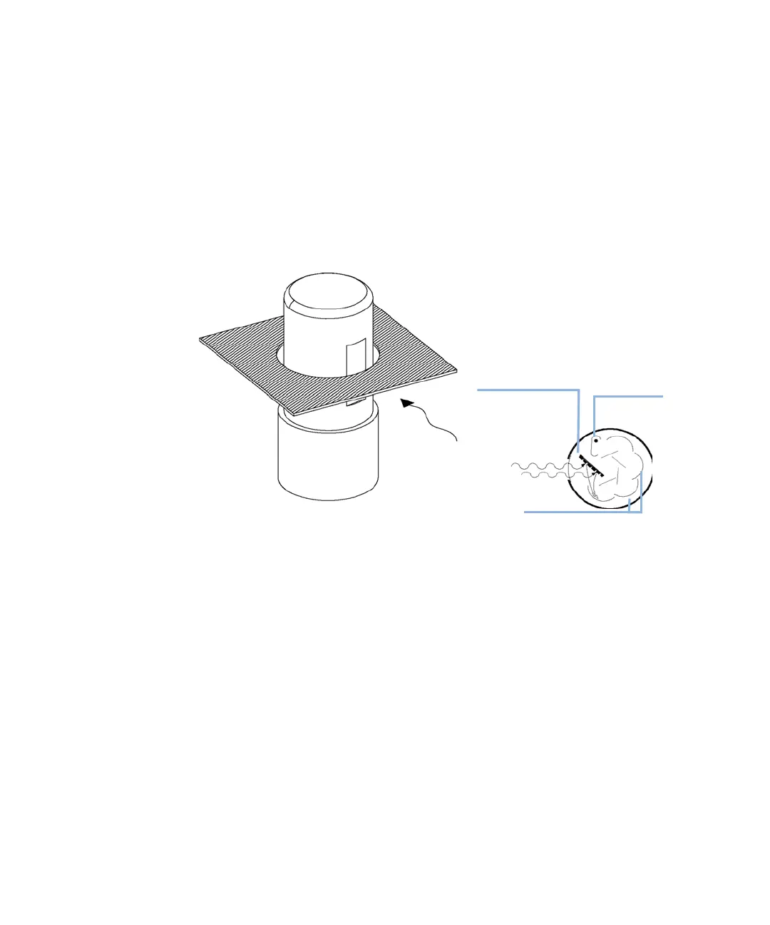
On the photocathode, Figure 12 on page 25, incident photons generate
electrons. These electrons are accelerated by an electrical field between
several arc-shaped dynodes. Depending on the voltage difference between any
pair of dynodes, an incident electron may spark-off further electrons which
accelerate onto the next dynode. An avalanche effect results: finally so many
electrons are generated that a current can be measured. The amplification is a
function of the voltage at the dynodes and is microprocessor controlled. You
can set the amplification using the PMTGAIN function.
Figure 12 Photo-multiplier Tube
This type of so-called side-on photo-multiplier is compact ensuring fast
response, conserving the advantages of the short optical path shown in
Figure 7 on page 20.
PMTs are designed for specific wavelength ranges. The standard PMT offers
optimum sensitivity from 200 to 600 nm. In the higher wavelength range a
red-sensitive PMT can improve performance.
,QFLGHQWOLJKW
SKRWRFDWKRGH
2SDTXH
$QRGH
,QFLGHQWOLJKW
$UFVKDSHGG\QRGHV
 Loading...