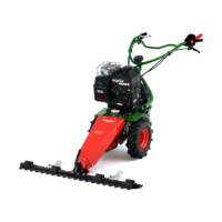
agria Multi-Purpose Machine 400P 29
3. Devices and Operating Elements
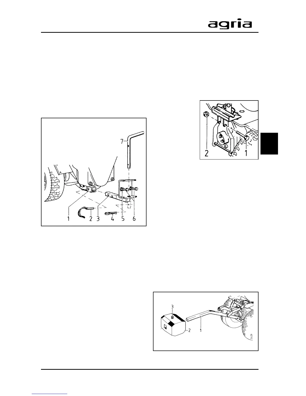
1 Weight support
2 Weight
3 Clamping bolt
1 Rectangular tube
2 Linch pin
3 Square pin
4 W-clip
5 Lock nut
6 Set screw
3
Rear Attachments
Most rear attachments are linked to the
hitch with a pin (7) (accessory).
The coupling unit (3) is inserted into the
rectangular tube (1) underneath the V-
belt guard.
Insert square pins (3) into the rectan-
gular tube (1) to a stop and lock with a
linch pin (2).
The angle through which some attach-
ments, like the depth bar or the plough,
pivot is set by adjusting screws (6) and
lock nuts (5) accordingly.
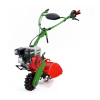
Front Weight
A front weight can be mounted to coun-
terbalance the weight of rear attach-
ments and to improve traction.
The front weight support is fitted to the
front attachment flange.
For first assembly, fit the hex bolt (1) to-
gether with hex
nut (2) into the
front attachment
flange. The bolt
serves as a cou-
pling pin to cou-
ple the attach-
ment using fast
tensioning de-
vices.
The hex bolt remains in its place when
the weight support is removed.
Fitting the weight support
l
Fit the weight support to the front
attachment flange with the central quick
tensioning device.
l
Push the front weight (2) onto the
square pin (1) and squeeze tight with
hex bolt (3).
Removing the weight support
When removing the weight support, the
weight can stay mounted on it. To re-
move the weight support, open the
quick tensioning device.
 Loading...